A cutting device for aluminum alloy window frame processing
A cutting device, aluminum alloy technology, applied in the direction of shearing device, metal processing equipment, metal processing machinery parts, etc., to achieve the effect of ensuring the collection effect
- Summary
- Abstract
- Description
- Claims
- Application Information
AI Technical Summary
Problems solved by technology
Method used
Image
Examples
Embodiment 1
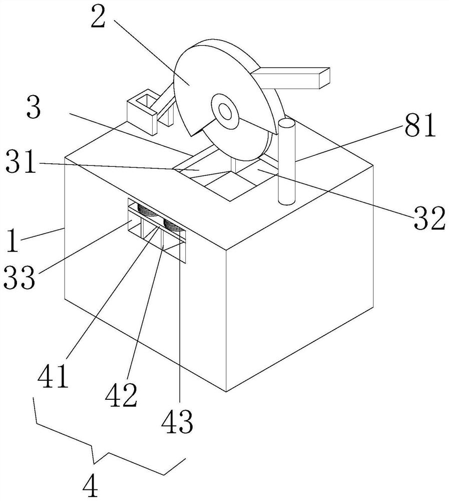
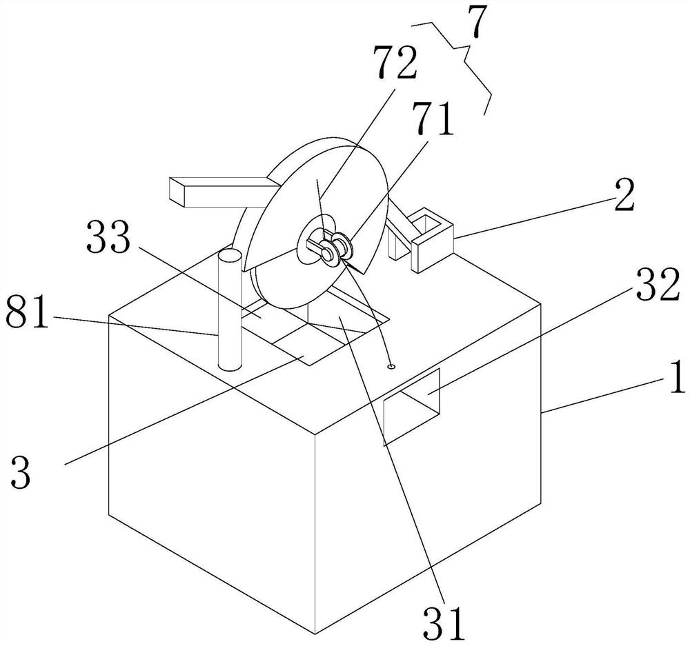
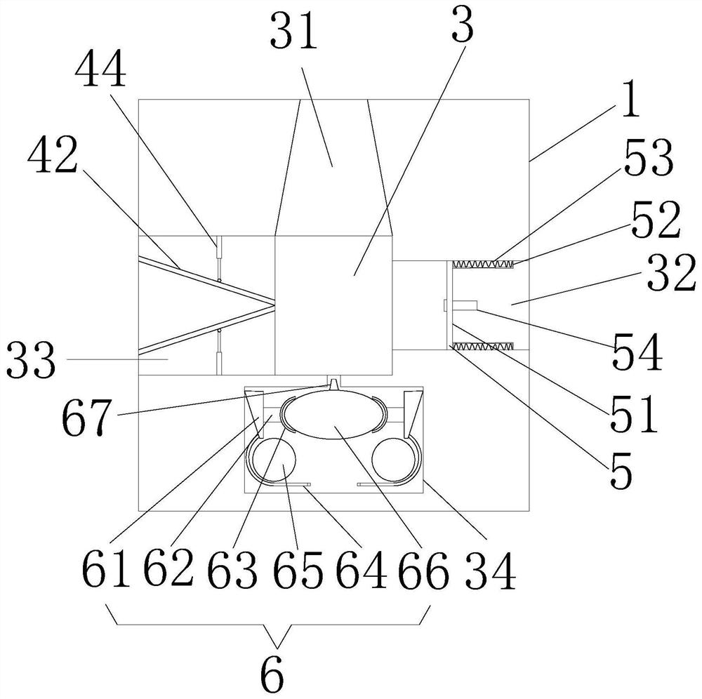
[0028] Example 1: Please refer to Figure 1-4 , a cutting device for aluminum alloy window frame processing, comprising a cutting table 1 and a cutting machine 2, the cutting machine 2 is arranged above the cutting table 1, and the cutting machine 2 and the cutting table 1 are flexibly connected, and the cutting table 1 is located on the cutting table The position below the cutting knife of the machine 2 is provided with a cutting groove 3, and the cutting groove 3 is respectively provided with an air outlet groove 34, a dust collection groove 31, an inlet groove 33 and a positioning groove 32, and the inlet groove 33 and the positioning groove 32 run through the cutting table respectively 1 The left and right sides are opened, the clamping mechanism 4 is arranged in the inlet groove 33, the positioning interlocking mechanism 5 is arranged in the positioning groove 32, the air outlet mechanism 6 is arranged in the air outlet groove 34, and the dust collecting groove 31 is arran...
Embodiment 2
[0029] Embodiment 2: On the basis of Embodiment 1, please refer to figure 1 and image 3 , the clamping mechanism 4 includes a height clamping plate 41, the height clamping plate 41 is a plate whose width matches the width of the inlet slot 33, a height limiting spring 43 is arranged above the height clamping plate 41, and the height limiting spring 43 is along the The upper surface of the height clamping plate 41 is laid, and one end of the height limiting spring 43 is fixedly connected with the height clamping plate 41, the other end of the height limiting spring 43 is fixedly connected with the upper wall of the inlet groove 33, and the height clamping plate 41 is arranged below There are two inclined clamping plates 42, the two inclined clamping plates 42 are arranged front and back, the length of the inclined clamping plates 42 matches the length of the inlet slot 33, and the side of the two inclined clamping plates 42 away from the cutting slot 3 is open Larger, that is...
Embodiment 3
[0030] Embodiment three: on the basis of embodiment two, please refer to image 3 , the width of the positioning groove 32 is adapted to the distance between the two telescopic connecting rods 44, the positioning linkage mechanism 5 includes a positioning plate 51, the length and height of the positioning plate 51 are adapted to the width and height of the positioning groove 32, The right side of the positioning plate 51 is provided with a movable telescopic frame 52, and the number of the movable telescopic frames 52 is two, and the two movable telescopic frames 52 are respectively arranged on the opposite wall surfaces of the front and rear sides of the positioning groove 32, and the two movable telescopic frames 52 are arranged All are provided with spring 53, and the left and right ends of spring 53 are respectively fixedly connected with the left and right ends of movable telescopic frame 52, and one end of movable telescopic frame 52 close to positioning plate 51 is fixed...
PUM
 Abstract
Description
Claims
Application Information
 - R&D
- Intellectual Property
- Life Sciences
- Materials
- Tech Scout
- Unparalleled Data Quality
- Higher Quality Content
- 60% Fewer Hallucinations
Browse by: Latest US Patents, China's latest patents, Technical Efficacy Thesaurus, Application Domain, Technology Topic, Popular Technical Reports.
© 2025 PatSnap. All rights reserved.Legal|Privacy policy|Modern Slavery Act Transparency Statement|Sitemap|About US| Contact US: help@patsnap.com


