Energy storage type direct coupling direct current transformer and control method

A DC transformer, output voltage control technology, applied in the direction of converting DC power input to DC power output, control/regulation systems, instruments, etc., can solve problems such as load power failure, cut-off fault short-circuit current, large short-circuit current, etc.

Pending Publication Date: 2020-12-15
CHINA ELECTRIC POWER RES INST +2
View PDF0 Cites 0 Cited by
  • Summary
  • Abstract
  • Description
  • Claims
  • Application Information

AI Technical Summary

Problems solved by technology

[0003] The DC power grid is a "low inertia" system. If a DC fault occurs, a large short-circuit current may be generated, and it will instantly affect the entire DC power grid. It requires a high response time for the protection system. The traditional AC system protection method , such as overcurrent protection, distance protection and differential protection, etc., are not suitable for direct application to the DC power grid; and the DC power grid has a large scale, complex structure, diverse operation modes, and a large number of equipment, so it is not possible to simply use the two-terminal DC transmission system The protection method of cutting off the entire DC system from the AC side; at the same time, in the DC power transmission and distribution system, it is difficult to develop a large-capacity DC circuit breaker. In order to effectively prevent the rapid spread of DC faults, the DC converter is usually required to have fault protection and isolation. function to prevent fault transmission from endangering the normal power supply system; for sensitive loads of DC power consumption, such as data centers, semiconductor companies, high-end manufacturing companies, etc., not only DC-DC transformers are required to have the function of blocking DC fault current, but also DC-DC transformers are required. The DC transformer has the function of uninterrupted power supply, which improves the reliability of power supply to the load
[0004] At present, the existing direct-coupled DC transformers based on half-bridge sub-modules have high module utilization and low investment costs. However, when a short-circuit fault occurs on the high-voltage side, the half-bridge sub-module cannot cut off the faulty short circuit by blocking the converter. At the same time, the low-voltage DC side loses power, and the load is cut off, which seriously affects the reliability of the system.

Method used


Image

  • Energy storage type direct coupling direct current transformer and control method
  • Energy storage type direct coupling direct current transformer and control method
  • Energy storage type direct coupling direct current transformer and control method

Examples


Embodiment 1

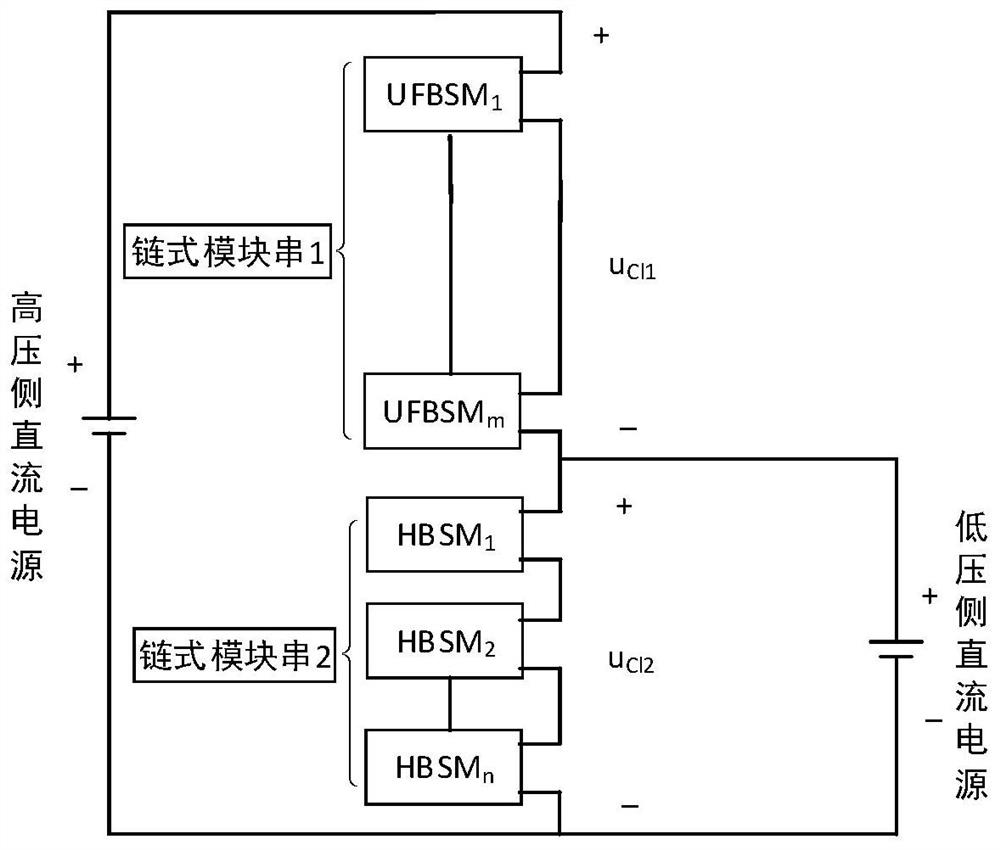
[0056] An energy storage type direct-coupled DC transformer provided by an embodiment of the present invention is as follows: figure 1 shown, including:

[0057] Chained module 1 and chained module 2;

[0058] The positive pole of the chain module 1 is connected to the positive pole of the high voltage side DC power supply;

[0059] The positive pole of the chain module 2 is respectively connected to the negative pole of the chain module 1 and the positive pole of the low-voltage side DC power supply; the negative pole of the chain module 2 is respectively connected to the negative pole of the high-voltage side DC power supply and the negative pole of the low-voltage side DC power supply;

[0060] The chain module 1 includes a plurality of unipolar full-bridge sub-modules connected in series; the chain module 2 includes a plurality of parallel energy storage type half-bridge sub-modules; each energy storage type half-bridge sub-module includes parallel Half bridge unit and e...

Embodiment 2

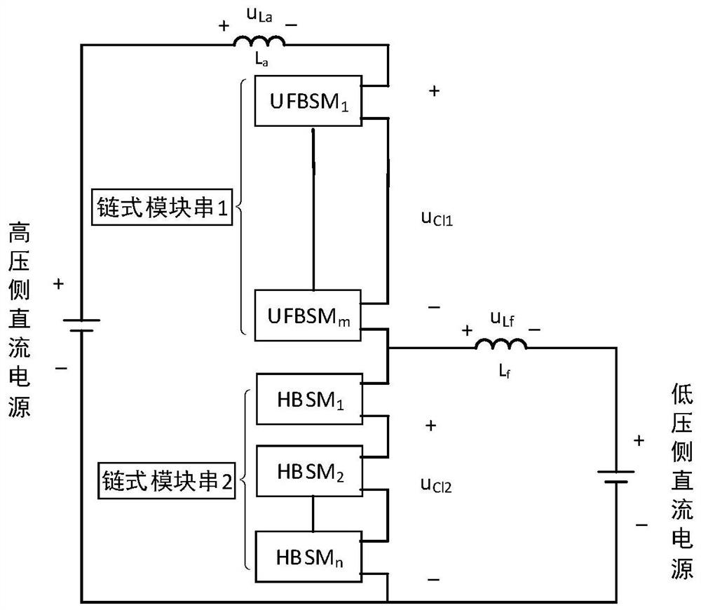
[0063] An energy storage type direct-coupled DC transformer provided by an embodiment of the present invention is as follows: image 3 shown, including:

[0064] Chain module 1, chain module 2, first filter inductor L a and the second filter inductor L f ;

[0065] The positive pole of the chain module 1 passes through the first filter inductor L a Connect to the positive pole of the DC power supply on the high voltage side;

[0066] The positive pole of the high-voltage side DC power supply is connected through the second filter inductor L f Connect with the positive pole of the chain module 1 and the negative pole of the chain module 2 respectively;

[0067] The positive pole of the chain module 2 is connected to the negative pole of the chain module 1; the negative pole of the chain module 2 is respectively connected to the negative pole of the high-voltage side DC power supply and the negative pole of the low-voltage side DC power supply;

[0068] The chain module 1 ...

Embodiment 3

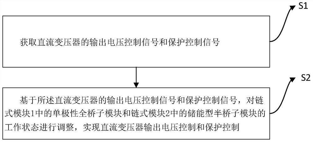
[0076] The embodiment of the present invention discloses a control method of an energy storage type direct-coupled DC transformer such as figure 2 shown, including:

[0077] S1 obtains the output voltage control signal and the protection control signal of the DC transformer;

[0078] S2 adjusts the working states of the unipolar full-bridge sub-module in the chain module 1 and the energy storage half-bridge sub-module in the chain module 2 based on the output voltage control signal and the protection control signal of the DC transformer, Realize DC transformer output voltage control and protection control;

[0079] The working state of the unipolar full-bridge sub-module includes: input, bypass and blocking;

[0080] The working state of the energy storage type half-bridge sub-module includes: putting into energy storage for charging, putting into energy storage for discharging, bypassing and blocking.

[0081] The output voltage control signal is generated by voltage clos...


PUM


Abstract

The invention provides an energy storage type direct coupling direct current transformer and a control method. The energy storage type direct coupling direct current transformer comprises a chain typemodule 1 and a chain type module 2, wherein the chain type module 1 comprises a plurality of unipolar full-bridge sub-modules which are connected in series; the chain type module 2 comprises a plurality of energy storage type half-bridge sub-modules which are connected in parallel; each energy storage type half-bridge sub-module comprises a half-bridge unit and an energy storage type unit which are connected in parallel, and the isolation of short-circuit fault current can be realized by adopting the unipolar full-bridge sub-module and the energy storage type half-bridge sub-module to construct the direct coupling type direct-current transformer; and meanwhile, uninterrupted power supply under a high-voltage side short-circuit fault and peak load shifting in the power supply process underthe normal operation condition can be realized through the energy storage type sub-module, so power supply reliability is improved, and meanwhile, the probability of power failure of low-voltage sideusers is reduced.

Description

technical field [0001] The invention belongs to the technical field of direct-current transmission, and in particular relates to an energy storage type direct-coupled direct-current transformer and a control method. Background technique [0002] The development of the DC grid is still limited by the lag of key equipment such as DC circuit breakers and DC transformers, among which DC transformers are of great significance for connecting different DC lines to form a DC grid. Compared with the traditional AC grid, it can be found that there are multiple different voltage levels in the AC grid, among which the higher voltage level is used for long-distance power transmission, while the lower voltage level is used for power distribution and power consumption. Similarly, in order to reduce the transmission loss in the DC power grid, a higher DC voltage level is required from the power generation center to the load center, while a lower voltage level should be used in the distribut...

Claims


Application Information

Patent Timeline
IPC IPC(8): H02M3/158
CPCH02M3/1584
Inventor 陶以彬李官军徐伟凡殷实詹昕刘忠
Owner CHINA ELECTRIC POWER RES INST
Why Eureka
Try Eureka