
Energy-saving and environment-friendly chemical water pollution treatment equipment

A technology of energy saving, environmental protection and treatment equipment, applied in the field of water pollution treatment, can solve the problems of reducing the diameter of the concave pipe, affecting the flow speed of sewage and the discharge volume, etc.

Inactive Publication Date: 2020-12-15
王文雄
View PDF0 Cites 2 Cited by
  • Summary
  • Abstract
  • Description
  • Claims
  • Application Information

AI Technical Summary

Problems solved by technology

[0005] In order to solve the above-mentioned technology, chemical factories will discharge waste materials such as mercury and lead along the water flow to the water pollution treatment equipment during processing, and the density of lead powder or lead particles is higher than that of water, resulting in the discharge process. Precipitation in the concave pipe of the treatment equipment reduces the diameter of the concave pipe and affects the flow velocity of the sewage and the actual discharge volume.

Method used


Image

  • Energy-saving and environment-friendly chemical water pollution treatment equipment
  • Energy-saving and environment-friendly chemical water pollution treatment equipment
  • Energy-saving and environment-friendly chemical water pollution treatment equipment

Examples


Embodiment 1

[0026] as attached figure 1 To attach Figure 5 Shown:

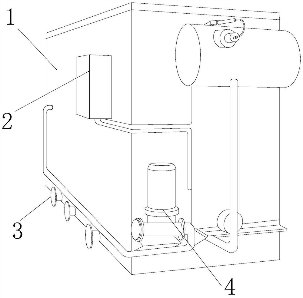
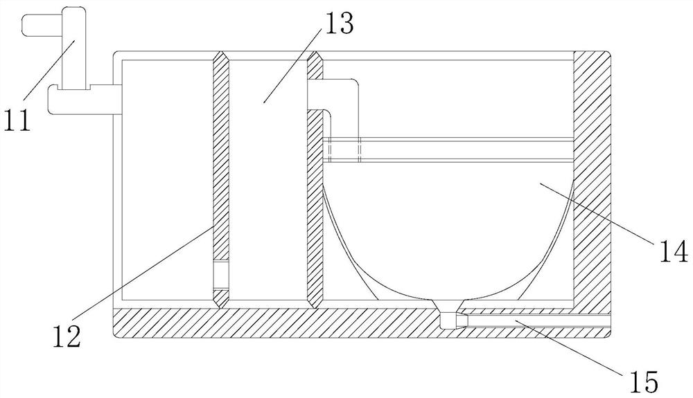
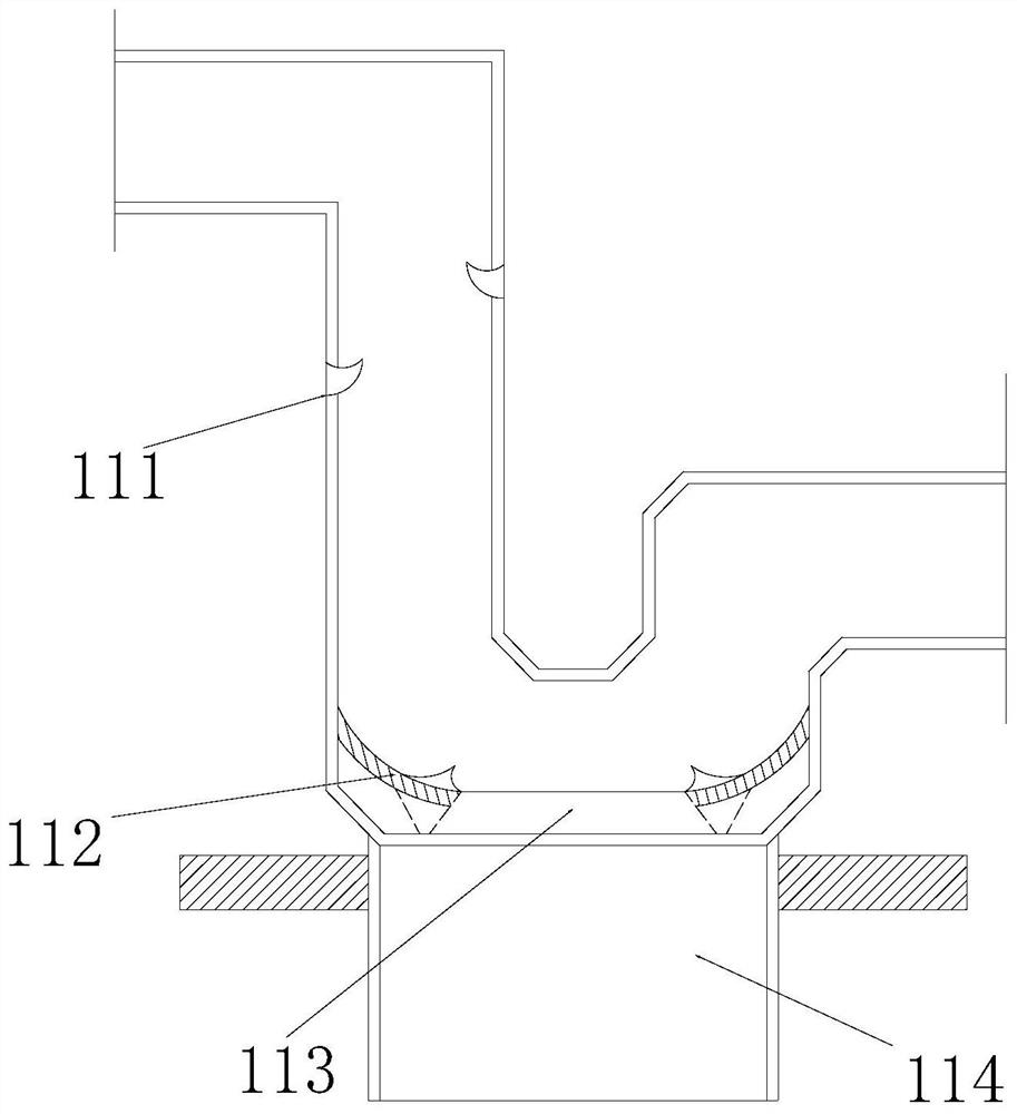
[0027] The present invention provides an energy-saving and environment-friendly chemical water pollution treatment equipment, the structure of which includes a treatment bin 1, a control box 2, a water outlet 3, and a motor 4, the control box 2 is fixedly installed on the left end surface of the outer side of the treatment bin 1, and the The control box 2 is located directly above the water outlet 3, the water outlet 3 is embedded and installed on the outer lower end surface of the processing chamber 1, the motor 4 is located under the right side of the control box 2, and the processing chamber 1 includes a sedimentation mechanism 11 , partition 12, oxidation chamber 13, sedimentation tank 14, sewage outlet 15, the sedimentation mechanism 11 is inlaid on the upper left side of the partition 12, and the outer end surface of the partition 12 is inlaid and mounted on the inner side of the processing chamber 1 On the end f...

Embodiment 2

[0033] as attached Figure 6 To attach Figure 8 As shown: the discharge mechanism 114 includes a movable plate 141, a closing mechanism 142, a slide rail 143, and a rotating shaft 144. The movable plate 141 is symmetrically installed on the inner upper end surface of the discharge mechanism 114, and the closing mechanism 142 is mounted on the On the left and right sides of the upper end of the movable plate 141, the slide rail 143 is inlaid on the inner end surface installed on the discharge mechanism 114, and the rotating shaft 144 is movably engaged and installed on the outer surface of the upper end of the slide rail 143, and the groove of the slide rail 143 The rail adopts a ladder-type symmetrical groove, which can effectively avoid the phenomenon of detachment during the sliding process while ensuring sliding.

[0034]Wherein, the closing mechanism 142 includes an inlaid magnetic groove 421, a ball 422, a closing plate 423, an inlaid shaft 424, and an elastic rope 425....


PUM


Abstract

The invention discloses energy-saving and environment-friendly chemical water pollution treatment equipment which structurally comprises a treatment bin, a control box, a water outlet and a motor, thecontrol box is fixedly embedded in the left end face of the outer side of the treatment bin and located over the water outlet, the water outlet is fixedly embedded in the lower end face of the outerside of the treatment bin, and the motor is located below the right side of the control box; when sewage flows into a sedimentation mechanism, the sewage impacts a leakage block, so that heavy metal debris in the sewage flows into the upper part of a filter screen in the leakage block to form accumulation, and water flows downwards along the filter screen to flow into the oxidation bin again, whenthe heavy metal debris impact the upper end face of the filter screen continually, a filling ring expands outwards along with the pressure to slowly discharge the heavy metal debris.

Description

technical field [0001] The invention belongs to the field of water pollution treatment, and more specifically relates to energy-saving and environment-friendly chemical water pollution treatment equipment. Background technique [0002] Chemical water pollution treatment equipment is a kind of use of peroxygen tank and filtration system to filter and recycle the sewage flowing into the equipment, so as to avoid the impact of sewage discharged into the river and the ecology. [0003] Based on the inventor's discovery above, the existing methods mainly have the following deficiencies, such as: due to the fact that waste materials such as mercury and lead will be discharged into the water pollution treatment equipment along the water flow in chemical plants during processing, and lead powder or The density of lead particles is higher than that of water, which causes them to settle on the concave pipe of the treatment equipment during the discharge process, reducing the diameter ...

Claims


Application Information

Patent Timeline
IPC IPC(8): C02F9/04C02F101/20
CPCC02F1/001C02F1/72C02F9/00C02F2001/007C02F2101/20
Inventor 王文雄
Owner 王文雄
Learn More