
Protective device installed on rear portion of vehicle

A protection device, a technology for the rear of a vehicle, applied to vehicle components, vehicle safety arrangements, bumpers, etc., can solve the problems of high mortality rate and low mortality rate, achieve low cost, reduce vehicle damage, and avoid damage

Inactive Publication Date: 2020-12-15
蔡金良
View PDF0 Cites 0 Cited by
  • Summary
  • Abstract
  • Description
  • Claims
  • Application Information

AI Technical Summary

Problems solved by technology

[0002] The height of the body of the truck is relatively high, and its height is just stuck in the position of the A-pillar of a normal car. Therefore, when a small vehicle rear-ends the truck, the front of the small vehicle will rush into the bottom of the truck, and the A-pillar will be bent by the collision. , and the A-pillar of a small vehicle corresponds to the position above the chest of the human body, so after the extrusion occurs, there will be very serious consequences, and the mortality rate is very high
[0003] In the existing technology, there is no good way to deal with this kind of collision. It can only remind the driver to pay attention to the distance between vehicles. However, the high incidence of such accidents tells us that there are not many drivers who can regulate driving in the society.

Method used


Image

  • Protective device installed on rear portion of vehicle
  • Protective device installed on rear portion of vehicle
  • Protective device installed on rear portion of vehicle

Examples


Embodiment 1

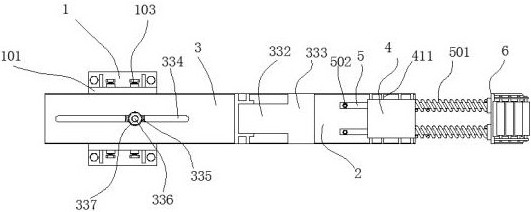
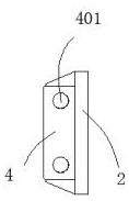
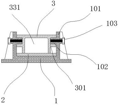
[0033] A protection device installed at the rear of a vehicle, including connectors 1 installed on both sides of the vehicle girder, the connector 1 is made of Q235 ordinary carbon structural steel with a wall thickness of 6mm~12mm; the connection between the connector 1 and the vehicle girder is made of Bolting or welding is fixed; and the steel plate 2 assembled in the connecting piece 1, the surface of the connecting piece 1 is casted with two upper and lower clamping plates 101, the two clamping plates 101 Sliders 102 are arranged on the opposite surfaces, and screw holes passing through the sliders 102 are arranged on the outside of the clamping plate 101, and screws 103 are assembled in the screw holes; the surface of the steel plate 2 is welded There is a shell plate 3, the upper and lower ends of the shell plate 3 are casted to form a chute 301, the slider 102 fits the chute 301, the screw 103 is screwed in and resists the chute 301, at this time the The shell plate 3 ...

Embodiment 2

[0035]A cavity 331 is formed between the shell plate 3 and the steel plate 2, and a rubber insert strip 332 is inserted into the cavity 331, and the right end of the insert strip 332 is injection-molded to form a terminal 333, so that There is a space between the end 333 and the steel pipe 5, and before the spring 501 is compressed to the limit, the steel pipe 5 contacts the end 333; a bar-shaped groove 334 is arranged transversely on the surface of the shell plate 3, A baffle plate 335 is arranged in the cavity 331, and a bolt 336 is screwed into the upper end of the baffle plate 335, and a nut 337 is fitted after the upper end of the bolt 336 passes through the strip groove 334, and the nut 337 After tightening, the baffle plate 335 is fixed; the effect of the above structure is that when the force of the collision is too large, the spring will be compressed rapidly. Damage to the spring. For this reason, we designed the above-mentioned structure. In the above-mentioned str...

Embodiment 3

[0037] An inner hole 338 is arranged in the end head 333, and an inner ring piece 339 is formed by injection molding inside the inner hole 338. The inner hole 338 passes through the end head 333 to the right, and the diameter of the inner hole 338 greater than the outer diameter of the steel pipe 5, the inner diameter of the inner ring piece 339 is smaller than the outer diameter of the steel pipe 5; the inner hole 338 can enter the steel pipe, and the steel pipe squeezes the inner ring piece 339 one by one after insertion to achieve the effect of deceleration If the above-mentioned structure is not set, then the nozzle of the steel pipe 5 has a shear force, which may cause the steel pipe 5 to be inserted into the end, and cause the connection between the steel pipe 5 and the end. bomb.


PUM


Abstract

The invention discloses a protective device installed on the rear portion of a vehicle. The protective device comprises connecting pieces installed on the two sides of a vehicle girder, and steel plates assembled in the connecting pieces. The connecting pieces are made of Q235 common carbon structural steel, the wall thickness of each connecting piece is 6 mm-12 mm, and the connecting pieces are fixed to the vehicle girder in a bolting or welding manner. An upper clamping plate and a lower clamping plate are formed on the surface of each connecting piece in a casting manner, wherein sliding blocks are arranged on the opposite faces of the two clamping plates, and screw holes penetrating through the sliding blocks are formed in the outer sides of the clamping plates. The device does not influence the use of the truck, and can perform buffering and energy absorption to protect a small vehicle when the small vehicle collides with the truck.

Description

technical field [0001] The invention relates to a protection device installed at the rear of a vehicle. Background technique [0002] The height of the body of the truck is relatively high, and its height is just stuck in the position of the A-pillar of a normal car. Therefore, when a small vehicle rear-ends the truck, the front of the small vehicle will rush into the bottom of the truck, and the A-pillar will be bent by the collision. , and the A-pillar of a small vehicle corresponds to the position above the chest of the human body, so after the extrusion occurs, very serious consequences will occur, and the mortality rate is very high. [0003] In the prior art, there is no good way to deal with this kind of collision, and the driver can only be reminded to pay attention to the distance between vehicles. However, such frequent accidents tell us that there are not many drivers who can regulate driving in society. [0004] For this reason, we have designed a kind of protec...

Claims


Application Information

Patent Timeline
Patent Type & Authority Applications(China)
IPC IPC(8): B60R19/56B60R19/24B60R19/02B60R19/04B60R19/16
CPCB60R19/023B60R19/04B60R19/16B60R19/24B60R19/56
Inventor 不公告发明人
Owner 蔡金良
Learn More