
Device and method for removing carbon dioxide in urea and polyol reaction tail gas

A carbon dioxide and polyol technology, applied in chemical instruments and methods, separation methods, gas treatment, etc., can solve the problems of removal, lower liquid ammonia yield, consumption of ammonia gas, etc. Good effect, complete removal effect

Inactive Publication Date: 2020-12-15
山西中科惠安化工有限公司
View PDF6 Cites 2 Cited by
  • Summary
  • Abstract
  • Description
  • Claims
  • Application Information

AI Technical Summary

Problems solved by technology

[0003] However, so far, except that Chinese patent CN110817900A discloses a feasible separation device and method for ammonia containing carbon dioxide and organic matter, people have not yet proposed other reasonable and effective methods for removing carbon dioxide in the tail gas of urea and polyol reaction
Although the Chinese patent CN110817900A method is feasible, due to the generation of ammonium carbonate, ammonia gas is consumed and the yield of liquid ammonia is reduced

Method used


Image

  • Device and method for removing carbon dioxide in urea and polyol reaction tail gas
  • Device and method for removing carbon dioxide in urea and polyol reaction tail gas

Examples


Embodiment 1

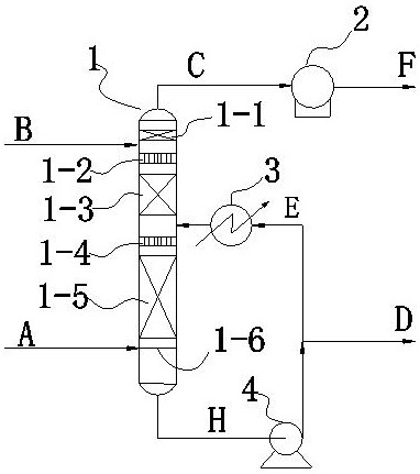
[0044] figure 1 A one-stage circulating caustic scrubbing carbon removal device is shown.

[0045] The one-stage circulating alkali washing carbon removal device includes an alkali washing tower 1 , a vacuum pump 2 , an alkali washing circulating liquid cooler 3 , and an alkali washing liquid circulating pump 4 .

[0046] One-stage circulating alkali cleaning carbon removal device The inside of the alkali washing tower 2 is provided with a demister 1-1, a fresh lye liquid distributor 1-2, a fresh lye alkali washing packing 1-3, and an alkali washing Circulating liquid distributor 1-4, alkali washing circulating liquid alkali washing packing 1-5, gas distributor 1-6.

[0047] The upper part of the alkali washing tower kettle of the one-stage circulating alkali cleaning decarbonization device is adjacent to the alkali washing circulating fluid and the lower part of the alkali washing packing is provided with an inlet for the reaction tail gas A of urea and polyol connected to t...

Embodiment 2

[0051] The pressure of the alkali washing tower 1 is controlled at -30kPaG, B is an aqueous solution of sodium hydroxide with a concentration of 15wt%, C is the tail gas produced by the reaction of urea and 1,2-propylene glycol, the temperature of the alkali washing tower is controlled at 40°C, and the liquid H in the bottom of the tower is The concentration of sodium hydroxide is controlled at 1wt%, and all the other processes are as described in Example 1. Analyze the composition of the gas C at the top of the alkali washing tower 1, which does not contain carbon dioxide.

Embodiment 3

[0053] The pressure of the alkali washing tower 1 is controlled at -70kPaG, B is an aqueous solution of sodium hydroxide with a concentration of 30wt%, C is the tail gas produced by the reaction of urea and glycerin, the temperature of the alkali washing tower is controlled at 10°C, and the sodium hydroxide in the tower still liquid H Concentration is controlled at 2wt%, and all the other processes are as described in Example 1. Analyze the composition of the gas C at the top of the alkali washing tower 1, which does not contain carbon dioxide.


PUM


Abstract

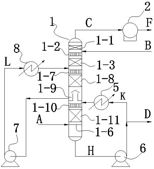
The invention discloses a device and a method for removing carbon dioxide in tail gas containing ammonia gas, carbon dioxide, polyhydric alcohol and cyclic carbonate generated in the process of preparing cyclic carbonate through reaction of urea and polyhydric alcohol. Carbon dioxide in the tail gas is converted into a carbonate aqueous solution, so that the problem that equipment and pipelines are blocked due to the fact that ammonia in the tail gas reacts with carbon dioxide at a low temperature to generate ammonium salt in the process of preparing cyclic carbonate from urea and polyol is solved. The method has the advantages of high feasibility, no ammonia consumption in the carbon dioxide removal process, simplicity, great convenience, high efficiency, easiness in control, thorough carbon dioxide removal, smooth tail gas post-treatment system and the like.

Description

technical field [0001] The invention relates to a device and method for removing carbon dioxide in the reaction tail gas of urea and polyols, in particular to a method for removing ammonia, carbon dioxide, polyols and The invention relates to a device and a method for removing carbon dioxide in tail gas of cyclic carbonates, belonging to the field of chemical industry. Background technique [0002] Cyclic carbonates, namely cyclic organic carbonates such as ethylene carbonate, propylene carbonate, and glycerol carbonate, are an important class of fine chemical products and raw materials for organic synthesis. Its traditional preparation method is synthesized by the reaction of phosgene and polyol (phosgene method), and it can also be synthesized by epoxy compounds such as ethylene oxide or propylene oxide and CO 2 reaction to prepare (epoxy compound method). However, due to the high toxicity of phosgene, the phosgene method was also eliminated. And because ethylene oxide ...

Claims


Application Information

Patent Timeline
IPC IPC(8): B01D53/78B01D53/62B01D53/96
CPCB01D53/78B01D53/62B01D53/96B01D2251/304B01D2251/404B01D2251/604B01D2257/504Y02A50/20Y02C20/40
Inventor 肖福魁李绍果刘磊
Owner 山西中科惠安化工有限公司
Learn More