
Antenna device and using method thereof

An antenna device and antenna unit technology, which is applied in the direction of antenna grounding switch structure connection, radiation element structure, etc., can solve the problems of large size, large volume, and low normal phase gain of the antenna.

Active Publication Date: 2020-12-11
BEIJING INST OF RADIO MEASUREMENT
View PDF12 Cites 0 Cited by
  • Summary
  • Abstract
  • Description
  • Claims
  • Application Information

AI Technical Summary

Problems solved by technology

[0004] Although many traditional wireless communication antennas can work in multiple wireless frequency bands, their working frequency bands are very narrow and can only cover one working frequency band, and there are still requirements for large form size, high processing cost, high profile or machining accuracy High-level defects, and the radiation pattern will split when working at high frequency, which will affect the electromagnetic radiation characteristics and lead to problems such as a decrease in antenna gain
For example, the traditional bow-tie antenna is a planar structure of a biconical antenna with a large volume. Generally, a sheet-like printed vibrator is used. The arms of the antenna are triangular sheets spread out on the same plane, and a distributed parameter transmission line is formed between the two triangular sheets. , the ratio of the distributed inductance and capacitance extending outward from the feed end remains constant, so the characteristic impedance along the line remains unchanged, with a bandwidth limitation, and the size of the traditional bow tie antenna is related to the lowest frequency wavelength of the antenna’s working frequency band, the antenna does not add a guide In the case of the reflective structure, the antenna normal phase gain is low

Method used


Image

  • Antenna device and using method thereof
  • Antenna device and using method thereof
  • Antenna device and using method thereof

Examples


Embodiment Construction

[0030] The technical solutions in the embodiments of the present invention will be clearly and completely described below in conjunction with the accompanying drawings in the embodiments of the present invention. Obviously, the described embodiments are only part of the embodiments of the present invention, not all of them. Based on the implementation manners in the present invention, all other implementation manners obtained by persons of ordinary skill in the art without making creative efforts belong to the scope of protection of the present invention.

[0031] It should be noted that the following disclosure provides many different implementations or examples for implementing different features of the present invention. Specific examples of components and arrangements are described below to simplify the present disclosure. Of course, these are examples only and are not intended to limit the invention. For example, in the following description, the "coupling" of a first co...


PUM


Abstract

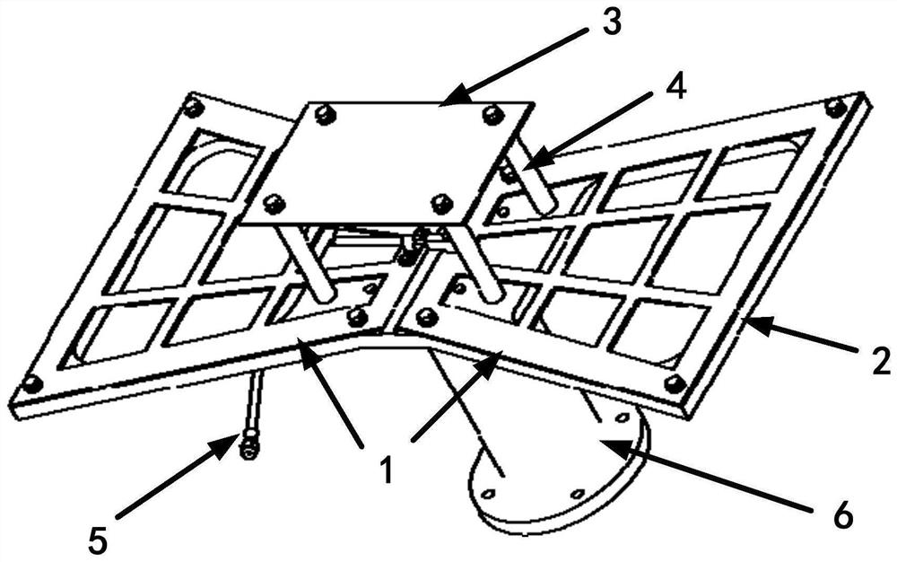
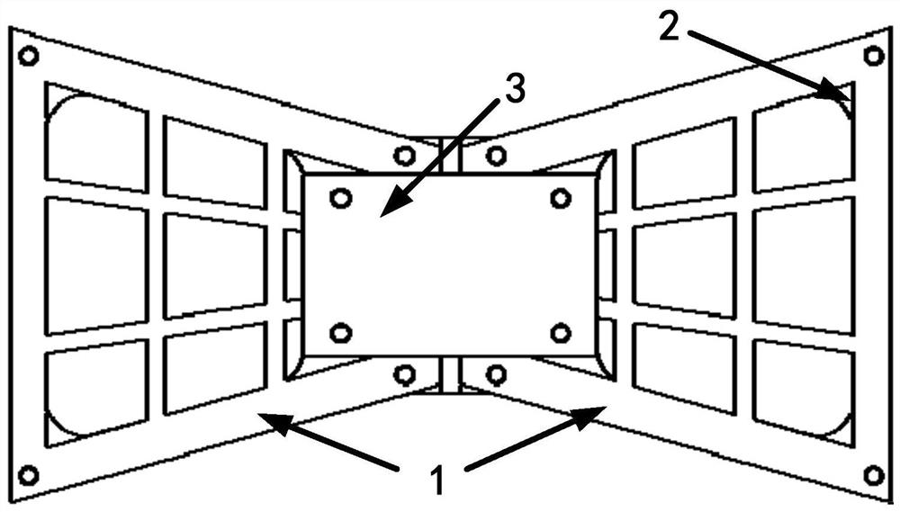
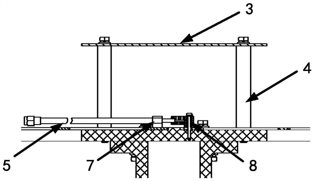
The invention provides an antenna device and a use method thereof. The antenna device comprises a first antenna unit radiation arm, a second antenna unit radiation arm and a feed structure, the feed structure comprises a first feed connecting piece and a second feed connecting piece, and the first feed connecting piece and the second feed connecting piece can feed electric energy into the first antenna unit radiation arm and the second antenna unit radiation arm. A strip-shaped gap is formed between the first antenna unit radiation arm and the second antenna unit radiation arm close to each other. The antenna device provided by the invention has the advantages that the structure is simple, the realization and the application are easy, the insulation between the unit radiation arms at the two sides is ensured while the electric connection is ensured through the design of the feed structure, and the reliability of the antenna device is improved. The antenna device has good electromagnetic radiation characteristics in an ultra-wide frequency band, solves the problem that the radiation characteristics of a traditional planar biconical antenna are deteriorated when the traditional planar biconical antenna works at high frequency, and has the advantages of low requirement on antenna processing precision, simplicity in assembly and stable performance.

Description

technical field [0001] The present invention relates to the technical field of antennas, and more specifically, to an antenna device and a method for using the same. Background technique [0002] An antenna is a transformer that transforms a guided wave propagating on a transmission line into an electromagnetic wave propagating in an unbounded medium (usually free space), or vice versa. A component used in radio equipment to transmit or receive electromagnetic waves. Engineering systems such as radio communication, broadcasting, television, radar, navigation, electronic countermeasures, remote sensing, and radio astronomy, which use electromagnetic waves to transmit information, rely on antennas to work. [0003] With the rapid development of wireless communication technology, antennas, as an important part of wireless communication equipment, are key components that affect the overall performance of communication systems. They are widely used in systems such as global posi...

Claims


Application Information

Patent Timeline
Patent Type & Authority Applications(China)
IPC IPC(8): H01Q1/36H01Q1/50
CPCH01Q1/36H01Q1/50
Inventor 赵佳越陈章平周恩
Owner BEIJING INST OF RADIO MEASUREMENT
Learn More