
Wheel edge circular ring type service parking brake

A technology of parking brake and service brake, which is applied in the direction of brake type, axial brake, brake actuator, etc., and can solve the problem that the drum brake is not as good as the disc brake, the control lever occupies a large space, and the ability to stand on a slope Weakness and other problems, to achieve the effect of improving service braking performance, saving layout space, and reliable parking brake

Pending Publication Date: 2020-12-11
十堰戎马汽车特种传动有限公司
View PDF0 Cites 0 Cited by
  • Summary
  • Abstract
  • Description
  • Claims
  • Application Information

AI Technical Summary

Problems solved by technology

[0002] So far, the commonly used wheel-side parking brakes are called air-break brakes; there are two problems with it, one is that the drum brake is not as good as the disc brake, and the disc brake caliper is only one-third of a circle First, it has a small pressure-bearing area and limited braking ability. Second, it has an air chamber and a control lever that takes up a lot of space, especially when used on a bridgeless independent suspension vehicle, which takes up too much space for the chassis. bad arrangement
The air break brake commonly used on large transport vehicles has a small pressure bearing area on the one hand, and on the other hand, only one brake can be installed on the side of the double wheel, which cannot solve the problem of installing one on each of the two wheels. Due to the poor braking ability on the road, the sliding friction heats up seriously, and water is often used to cool down. In this way, in the cold winter in the north, the water flow will freeze the entire road, and the probability of accidents due to road slipping will increase. The safety factor is low and the slope is low. Weak ability

Method used


Image

  • Wheel edge circular ring type service parking brake
  • Wheel edge circular ring type service parking brake
  • Wheel edge circular ring type service parking brake

Examples


Embodiment Construction

[0024] Below in conjunction with accompanying drawing, further describe the present invention.

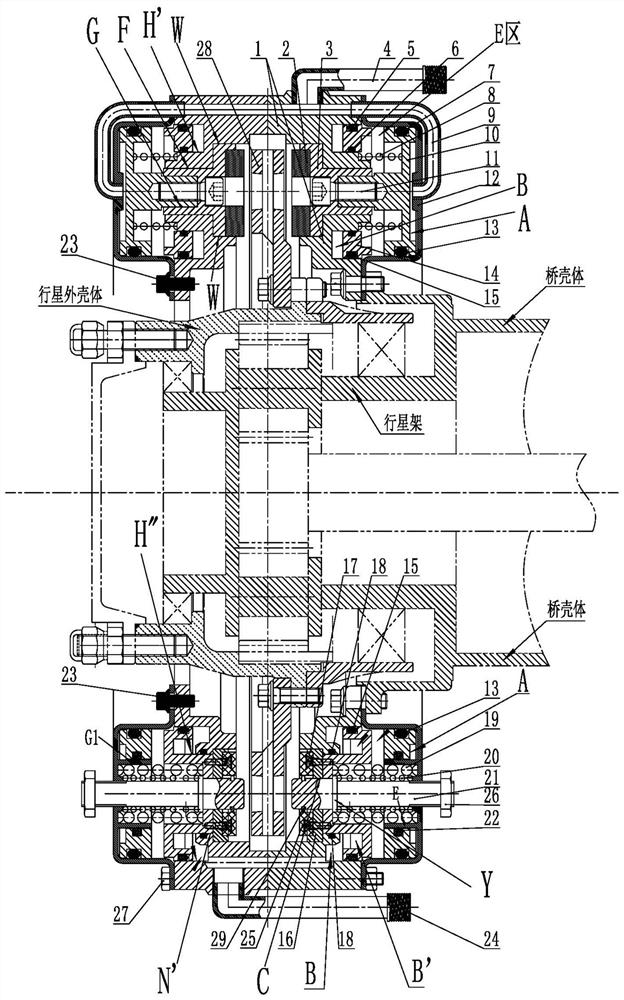
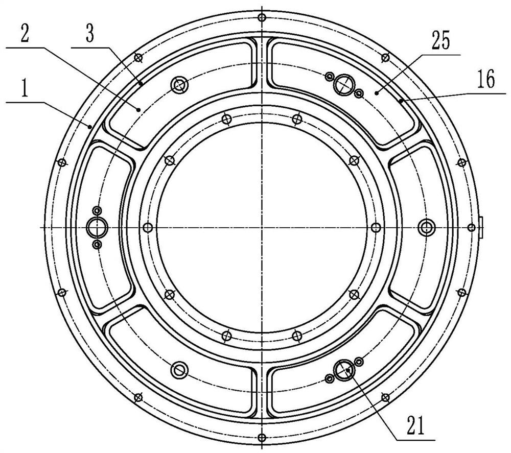
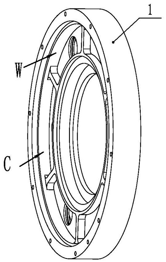
[0025] Such as figure 1 As shown in the present invention, the wheel rim ring type service parking brake, the left brake unit and the right brake unit which are symmetrically arranged on the left and right sides and have the same function and structure, respectively have driving brake units in the left brake unit and the right brake unit. Two systems of brake and parking brake, including housing 1, brake pad 2, service brake base plate 3, service brake main air pipe 4, first outer ring air seal 5, first small air seal ring 6, second Second outer ring air seal 7, service brake return spring 8, service brake bronchus 9, service brake air chamber disc 10, countersunk screw 11, ring cover 12, second inner ring air seal 13, parking brake air Disk 14, first inner ring air seal 15, parking brake bottom plate 16, screw 17, small parking air seal 18, parking brake return spring 19, taper p...


PUM


Abstract

The invention provides a wheel edge circular ring type service parking brake which comprises a left brake unit and a right brake unit which are symmetrically arranged at the left side and the right side. The functions and the structures of the left brake unit and the right brake unit are the same; the left brake unit and the right brake unit are each provided with a service brake system and a parking brake system; and a brake disc is arranged between the left brake unit and the right brake unit, shells of the left brake unit and the right brake unit are connected into a rigid body through longbolts, taper holes used for allowing pin shafts in the parking brake systems to be inserted therein are evenly distributed in the brake disc along the circumference, and the wheel edge circular ringtype service parking brake is formed, wherein a brake pad and a taper pin jointly complete the strong parking brake performance of the parking brake systems, reliable parking braking is achieved, theservice brake performance is improved, and the purposes of saving the arrangement space and reducing the self weight are achieved.

Description

technical field [0001] The invention belongs to the technical field of vehicle parking brakes, in particular to a wheel-rim circular ring type parking brake, which is applicable to all wheeled vehicles. Background technique [0002] So far, the commonly used wheel-side parking brakes are called air-break brakes; there are two problems with it, one is that the drum brake is not as good as the disc brake, and the disc brake caliper is only one-third of a circle First, it has a small pressure-bearing area and limited braking ability. Second, it has an air chamber and a control lever that takes up a lot of space, especially when used on a bridgeless independent suspension vehicle, which takes up too much space for the chassis. Not well arranged. The air break brake commonly used on large transport vehicles has a small pressure bearing area on the one hand, and on the other hand, only one brake can be installed on the side of the double wheel, which cannot solve the problem of i...

Claims


Application Information

Patent Timeline
Patent Type & Authority Applications(China)
IPC IPC(8): F16D55/2265F16D65/18F16D121/02
CPCF16D55/2265F16D65/18F16D2121/02
Inventor 周殿玺鞠传喜
Owner 十堰戎马汽车特种传动有限公司
Learn More