
Ship lock double-layer water conveying system with longitudinally-through drainage type lock bottom

A water conveyance system and through-type technology, applied in the field of double-layer water conveyance system of ship locks, can solve problems such as the berthing conditions of ships in lock chambers with bad water flow cavitation characteristics at diversion outlets, and achieve improved water conveyance safety and water conveyance efficiency, optimized The berthing conditions of ships and the effect of reducing water delivery energy

Active Publication Date: 2020-12-11
CHANGJIANG RIVER SCI RES INST CHANGJIANG WATER RESOURCES COMMISSION
View PDF4 Cites 2 Cited by
  • Summary
  • Abstract
  • Description
  • Claims
  • Application Information

AI Technical Summary

Problems solved by technology

[0007] In order to solve the problem of the worse cavitation characteristics of the water flow at the diversion port and the berthing conditions of the ship in the lock chamber caused by the greater water delivery energy of the ship lock, the present invention provides a double-layer water delivery system for the ship lock with longitudinally penetrating water outlet at the bottom of the lock. On the one hand It can greatly improve the pressure characteristics of the diversion port to effectively avoid cavitation and cavitation erosion. On the other hand, it can disperse the outflow to the greatest extent, improving the safety and efficiency of water delivery in the ship lock.

Method used


Image

  • Ship lock double-layer water conveying system with longitudinally-through drainage type lock bottom
  • Ship lock double-layer water conveying system with longitudinally-through drainage type lock bottom
  • Ship lock double-layer water conveying system with longitudinally-through drainage type lock bottom

Examples


Embodiment Construction

[0021] In order to make the purpose, technical solutions and advantages of the embodiments of the present invention clearer, the technical solutions in the embodiments of the present invention will be clearly and completely described below in conjunction with the drawings in the embodiments of the present invention. Obviously, the described embodiments It is a part of embodiments of the present invention, but not all embodiments. Based on the embodiments of the present invention, all other embodiments obtained by persons of ordinary skill in the art without making creative efforts belong to the protection scope of the present invention.

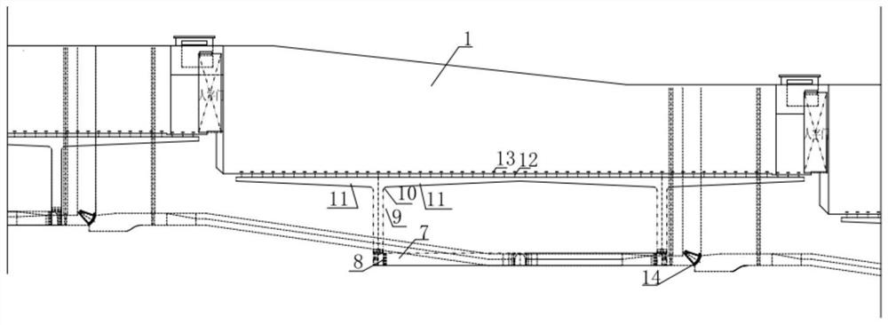
[0022] see Figure 1-5 , the embodiment of the present invention provides a double-layer water delivery system for a ship lock with vertically penetrating water outlet at the bottom of the lock, including a ship lock chamber 1, a main water delivery corridor 2, a water filling valve 3, a T-shaped pipe 4, a diverter partition 5, The first div...


PUM


Abstract

The invention relates to a ship lock double-layer water conveying system with a longitudinally-through drainage type lock bottom. The ship lock double-layer water conveying system comprises a ship lock chamber, a first diversion port, a middle branch gallery, a second diversion port, water conveying main galleries located on two sides of the ship lock chamber, filling valves arranged on the upstream portions of the water conveying main galleries, and drain valves arranged on the downstream portions of the water conveying main galleries; the water conveying main galleries communicate with an inlet of the first diversion port through T-shaped pipes, and an outlet of the first diversion port communicates with the second diversion port through the middle branch gallery; the second diversion port communicates with the third diversion port located in the upper layer through a vertical shaft, the third diversion port communicates with a water drainage branch gallery, and the water drainage branch gallery communicates with water drainage holes, and energy dissipation cover plates are arranged on the water drainage holes; and the elevations of the first diversion port, the middle branch gallery and the second diversion port are consistent with those of the drain valves, and the third diversion port, the water drainage branch gallery, the water drainage holes and the energy dissipation cover plates are located on the elevation surface of a lock chamber bottom plate. According to the ship lock double-layer water conveying system, the pressure characteristics of the diversion ports canbe improved to avoid cavitation and cavitation erosion, moreover, outflow can be dispersed to the maximum extent, and the water conveying safety and the water conveying efficiency of the ship lock are improved.

Description

technical field [0001] The invention relates to the technical field of water conservancy engineering, in particular to a double-layer water conveyance system for ship locks with vertically penetrating water outlets at the bottom of the locks. Background technique [0002] In order to overcome the water level difference caused by the construction of reservoir dams on navigable rivers, navigable structures, most commonly ship locks, need to be built. The operating principle of the ship lock is: through the water delivery system buried on both sides or bottom of the lock chamber, the lock chamber is filled and discharged with water, so that the water level of the lock chamber is equal to the water level of the upstream and downstream, and the ships docked in the lock chamber rise with the filling and discharging water. Or down, so as to overcome the water level difference formed by damming, and realize the upward and downward movement of the ship. [0003] The water conveyance...

Claims


Application Information

Patent Timeline
Patent Type & Authority Applications(China)
IPC IPC(8): E02C1/06E02C1/08
CPCE02C1/06E02C1/08
Inventor 江耀祖吴英卓王智娟杨伟刘志雄刘火箭李静何勇魏红艳
Owner CHANGJIANG RIVER SCI RES INST CHANGJIANG WATER RESOURCES COMMISSION
Learn More