Rapid molding equipment for plastic masterbatch production

A technology of molding equipment and plastic masterbatch, which is applied in the field of plastic processing, can solve the problems of reducing its own functionality, unfavorable transition installation operation, and inability to synchronize the screening operation of plastic masterbatch, so as to achieve the effect of improving its own functionality

Inactive Publication Date: 2020-12-11
伍尚华
View PDF4 Cites 1 Cited by
  • Summary
  • Abstract
  • Description
  • Claims
  • Application Information

AI Technical Summary

Problems solved by technology

[0004] The existing rapid prototyping equipment for plastic masterbatch production has certain disadvantages in the process of use. The traditional rapid prototyping equipment for plastic masterbatch production only has a single granulation function, so that the rapid prototyping equipment cannot process the processed plastic masterbatch. Synchronous screening operation reduces its own functionality; secondly, traditional rapid prototyping equipment for plastic masterbatch production adopts spliced ​​fixed structure design, which increases the difficulty of installation and disassembly of rapid prototyping equipment for plastic masterbatch production, which is not conducive to users Transition and installation of rapid prototyping equipment for plastic masterbatch production; at the same time, traditional rapid prototyping equipment for plastic masterbatch production does not have a rotary adjustment structure, making it impossible to perform screening and adjustment operations according to the particle size of plastic masterbatches, reducing the The flexibility of its use brings certain adverse effects to users

Method used


Image

  • Rapid molding equipment for plastic masterbatch production
  • Rapid molding equipment for plastic masterbatch production
  • Rapid molding equipment for plastic masterbatch production

Examples


Embodiment Construction

[0033] The technical solutions in the embodiments of the present invention will be clearly and completely described below in conjunction with the embodiments of the present invention. Apparently, the described embodiments are only some of the embodiments of the present invention, not all of them. Based on the embodiments of the present invention, all other embodiments obtained by persons of ordinary skill in the art without creative efforts fall within the protection scope of the present invention.

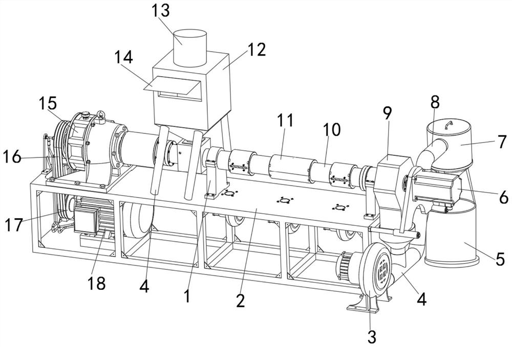
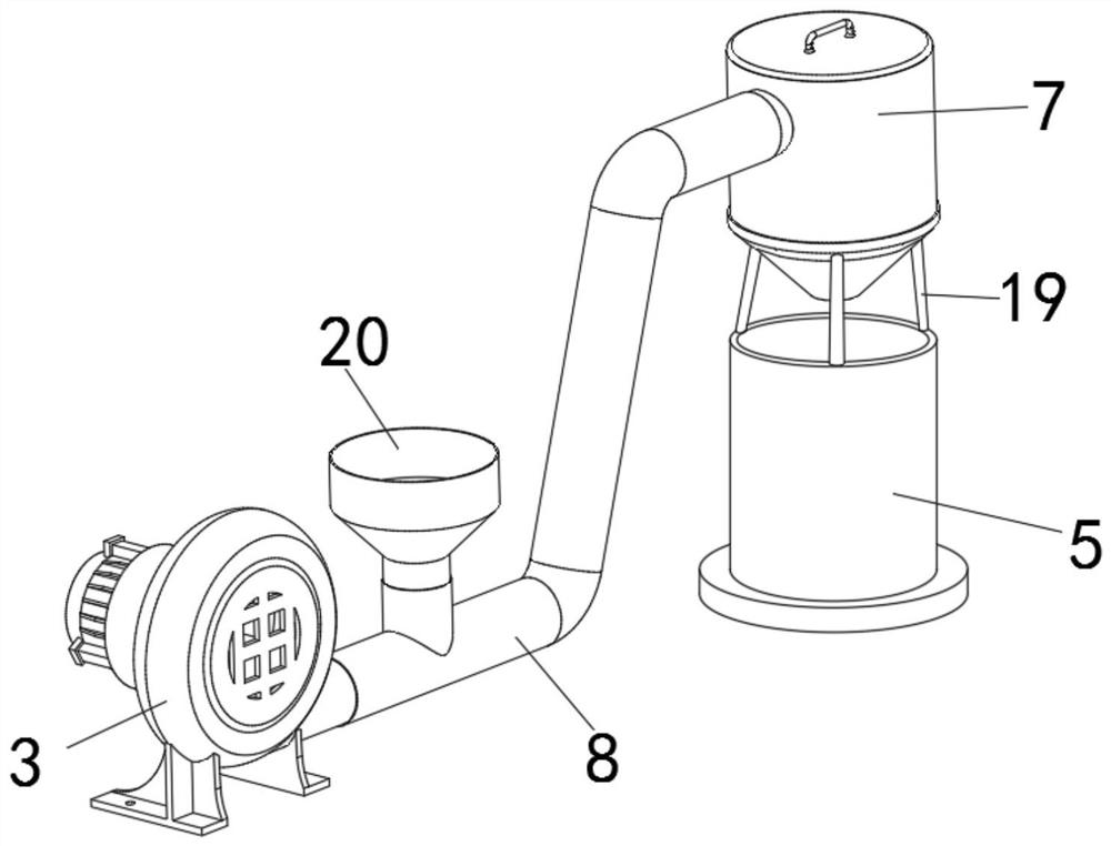
[0034] Such as Figure 1-7 As shown, a rapid prototyping equipment for the production of plastic masterbatches includes a fixed base 2, a splicing pipe 10 and a storage tank 5, the splicing pipe 10 is fixedly installed on the upper part of the fixed base 2, and the side outer surface of the splicing pipe 10 is fixedly installed There is a docking ferrule 11, and the outer surface of the splicing pipe 10 close to the side of the docking ferrule 11 is fixedly installed with two sets...


PUM


Abstract

The invention discloses rapid molding equipment for plastic masterbatch production. The rapid forming equipment comprises a fixing base, a splicing pipe and a storage barrel, wherein the splicing pipeis fixedly installed on the upper portion of the fixing base, a butt joint clamping sleeve is fixedly installed on the outer surface of the side edge of the splicing pipe, two sets of butt joint clamping bases are fixedly installed on the side, close to the butt joint clamping sleeve, of the outer surface of the splicing pipe, the storage barrel is fixedly installed at one end of the fixing base,a distribution barrel is fixedly installed at the upper end of the storage barrel, an air blower is fixedly installed on one side of the distribution barrel, a conveying pipe is fixedly installed between the distribution barrel and the air blower, the outer surface of the upper end of the conveying pipe is fixedly connected with a feeding hopper in a sleeving mode, and two groups of fixed lanternrings are fixedly mounted in the distribution barrel. The rapid forming equipment for plastic masterbatch production is provided with an auxiliary screening structure, the functionality of the rapidforming equipment is improved, meanwhile, the rapid forming equipment is provided with a rotary adjusting structure, and the flexibility of screening operation of the rapid forming equipment is improved.

Description

technical field [0001] The invention belongs to the technical field of plastic processing, and more specifically relates to a rapid prototyping device for the production of plastic master batches. Background technique [0002] The rapid prototyping equipment for plastic masterbatch production is a kind of rapid prototyping equipment for extrusion and granulation of plastic masterbatch during the production and processing of plastic masterbatch. The rapid prototyping equipment can effectively shorten the plastic masterbatch The time required for grain processing. [0003] A kind of plastic particle processing equipment disclosed in comparative document CN207403030U, its structure includes a base, a pelletizing bin and a smelting machine, a guide post, a fixing groove, a vibration-damping spring and a drive motor are arranged on the upper left of the base, and the guide post is fixed Connected to the upper left end of the base, the fixing groove is fixedly connected to the gu...

Claims


Application Information

Patent Timeline
Patent Type & Authority Applications(China)
IPC IPC(8): B29B9/06B29B13/04B29B13/10
CPCB29B9/06B29B13/10B29B13/045
Inventor 伍尚华
Owner 伍尚华
Why Eureka
Try Eureka