Surface repairing and grinding device and surface repairing and grinding method
A surface repair and grinding mechanism technology, which is applied in the direction of grinding drive devices, grinding machines, grinding slides, etc., can solve problems such as too much or too little grinding, uncontrollable grinding depth, and failure to achieve structural strength and rigidity.
- Summary
- Abstract
- Description
- Claims
- Application Information
AI Technical Summary
Problems solved by technology
Method used
Image
Examples
Embodiment 1
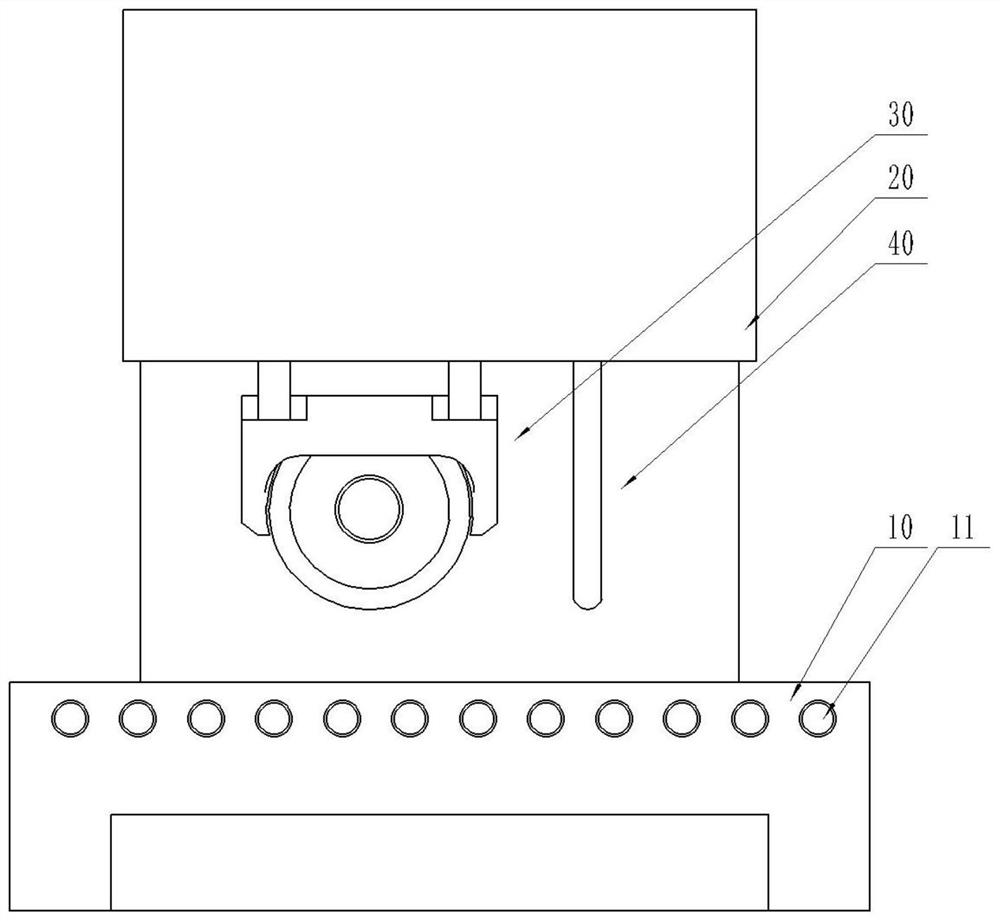
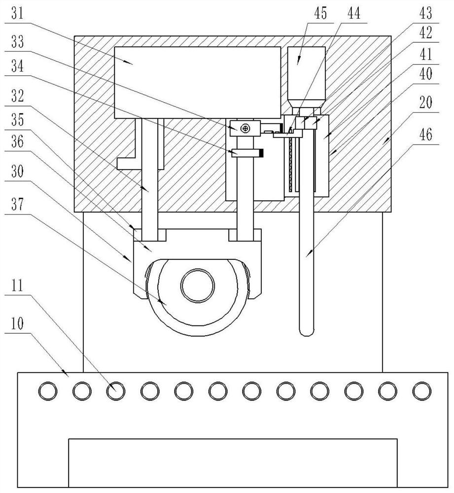
[0072] A surface repair grinding device, wherein, such as figure 1 , 2 As shown, it includes: a transfer seat 10, a top seat 20, a lifter 31, a mechanism 30, a grinding mechanism 36, and a limit mechanism 40.
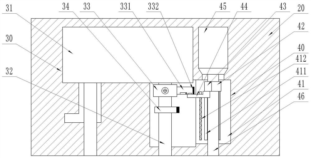
[0073] There are conveying rollers 11 on the conveying seat 10 , the conveying seat 10 is used for conveying workpieces to be processed, and the top seat 20 is arranged on the conveying seat 10 . The lifter 31 structure 30 is arranged in the top seat 20, and the lifter 31 structure 30 has: a lifter 31, a shaft column 32, and a matching sleeve 33.
[0074] Such as Figure 3-5 As shown, the shaft column 32 is connected to the elevator 31, and the matching sleeve 33 is fixed on the shaft column 32. The side of the matching sleeve 33 has a limiting plate 331, and the right side of the limiting plate 331 has a first magnetic block 332. The right end of the first magnetic block 332 is N pole.
[0075] The grinding mechanism 36 is fixedly connected to the shaft column 32 t...
Embodiment 2
[0089] A surface repairing and grinding device, which has the same characteristic structure as the first embodiment, and the grinding mechanism 36 also has a non-contact detection mechanism or a contact detection mechanism.
[0090] Such as Figure 11 As shown, the non-contact detection mechanism has a distance measuring sensor 38, which is arranged on the side end of the grinding wheel 37, and the distance measuring sensor 38 is connected to the alarm 381 through wired or wireless communication.
[0091] Such as Figure 12 As shown, the contact detection mechanism has a push block 39, the push block 39 is arranged on the side end of the grinding wheel 37, the push block 39 is provided with a pressure spring 391, and the right end of the push block 39 has a first electric piece 392, the first electric piece 392 Connect the alarm, the left end of the first electric sheet 392 has a second electric sheet 393, the second electric sheet 393 is connected to the power supply, the le...
Embodiment 3
[0096] A method for surface repair and polishing, comprising the following steps:
[0097] Put the defective workpiece to be processed into the transfer seat 10, so that the defect of the workpiece to be processed is aligned up and down with the probe 46 under the limit mechanism 40;
[0098] Push the connection block 42 to move down along the first slideway 411 of the slide seat 41 afterwards, so that the pressure block 43 on the connection block 42 pushes the limit block 44 to slide down along the second slideway 412 of the slide seat 41. The return spring in the two slides 412 is compressed, and then the probe 46 connected to the connection block 42 contacts with the defect of the workpiece to be processed, wherein, during the downward movement of the connection block 42 , the second on the left side of the connection block 42 The S pole of the magnetic block 421 reacts with the N pole at the right end of the magnetic column 414 in the lateral channel 413, and the magnetic ...
PUM
 Abstract
Description
Claims
Application Information
 - Generate Ideas
- Intellectual Property
- Life Sciences
- Materials
- Tech Scout
- Unparalleled Data Quality
- Higher Quality Content
- 60% Fewer Hallucinations
Browse by: Latest US Patents, China's latest patents, Technical Efficacy Thesaurus, Application Domain, Technology Topic, Popular Technical Reports.
© 2025 PatSnap. All rights reserved.Legal|Privacy policy|Modern Slavery Act Transparency Statement|Sitemap|About US| Contact US: help@patsnap.com


