Aircraft skin grinding device
A technology of aircraft skin and grinding wheel, which is applied in the direction of grinding drive device, grinding/polishing safety device, grinding machine, etc., which can solve the problem of low grinding accuracy and achieve the effect of controlling grinding depth and precise grinding depth
- Summary
- Abstract
- Description
- Claims
- Application Information
AI Technical Summary
Problems solved by technology
Method used
Image
Examples
Embodiment 1
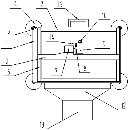
[0020] Referring to Figures 1-3, it is a schematic structural view of Embodiment 1 of the present invention, an aircraft skin grinding device, including a positioning frame 1, a carriage 2, a sliding beam 3, two pairs of vacuum suction cups 4, a first electronic slide rail 5, A pair of second electronic slide rails 6, a servo motor 7, a turntable 8, a grinding motor 9 and a grinding wheel 10, the positioning frame 1 and the sliding frame 2 are rectangular frames, and two pairs of the vacuum suction cups 4 are detachably connected to the positioning frame 1 at the four corners of the lower surface, the upper and lower sides of the lower surface of the carriage 2 are horizontally slidably connected to the positioning frame 1, and the first electronic slide rail 5 is arranged in one of the sliding connections between the carriage 2 and the positioning frame 1, And the connecting surface of the first electronic slide rail 5 is detachably connected with the positioning frame 1, the ...
Embodiment 2
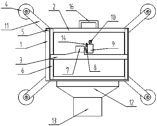
[0023] refer to Figure 2-3 Compared with Embodiment 1, this embodiment is different in that it also includes a connecting rod 11, one end of which is detachably connected to the four corners of the lower surface of the positioning frame 1, and the other end of the connecting rod 11 is detachably connected Vacuum suction cup4.
[0024] In actual use: when the damaged part of the aircraft skin is a hyperbolic skin, the suction position of the vacuum suction cup 4 can be changed through the connecting rod 11, so that the positioning frame 1 can be stably positioned on the aircraft skin.
Embodiment 3
[0026] Referring to Figure 1 and image 3 Compared with Embodiment 1 or 2, the difference of this embodiment is that: the positioning frame 1 is detachably connected with a recovery bucket 12, the recovery bucket 12 has an opening, and a recovery bag 13 is connected under the opening .
[0027] In actual use: there will be debris when the skin is polished, and the splashed debris can be collected through the recovery bucket 12, and the debris falls into the recovery bucket 12 and enters the recovery bag 13 below to complete unified recovery.
PUM
 Abstract
Description
Claims
Application Information
 - R&D Engineer
- R&D Manager
- IP Professional
- Industry Leading Data Capabilities
- Powerful AI technology
- Patent DNA Extraction
Browse by: Latest US Patents, China's latest patents, Technical Efficacy Thesaurus, Application Domain, Technology Topic, Popular Technical Reports.
© 2024 PatSnap. All rights reserved.Legal|Privacy policy|Modern Slavery Act Transparency Statement|Sitemap|About US| Contact US: help@patsnap.com


