
Optical fiber sensor based on hybrid cascade structure and preparation method

An optical fiber sensor, hybrid cascade technology, applied in instruments, scientific instruments, optical devices, etc., can solve problems such as increasing system complexity and cost, affecting sensor measurement accuracy, and measuring a single physical quantity, achieving good performance and simple structure. Compact, inexpensive effect

Inactive Publication Date: 2020-12-08
WUHAN INSTITUTE OF TECHNOLOGY
View PDF11 Cites 1 Cited by
  • Summary
  • Abstract
  • Description
  • Claims
  • Application Information

AI Technical Summary

Problems solved by technology

In the monitoring process, the detected spectrum is generally a single resonance peak. Therefore, when temperature and curvature affect the device at the same time, the resonance peak is cross-modulated. At this time, the change of a single physical quantity cannot be measured by the drift of the spectrum.
In addition, when one physical quantity is measured alone, the perturbation of another physical quantity will also cause errors in the measurement and affect the measurement accuracy of the sensor.
In this case, compensation processing is generally required, which increases the complexity and cost of the system

Method used


Image

  • Optical fiber sensor based on hybrid cascade structure and preparation method
  • Optical fiber sensor based on hybrid cascade structure and preparation method
  • Optical fiber sensor based on hybrid cascade structure and preparation method

Examples


Embodiment 1

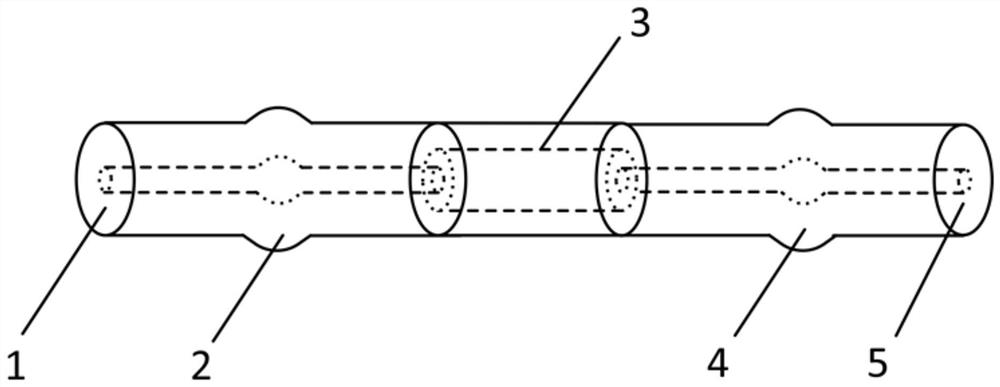
[0027] Embodiment one: if figure 1 As shown, based on the hybrid structure optical fiber sensor based on the hollow-core fiber cascaded with the fused-cone single-mode fiber, the fused-cone single-mode fiber-2 and the fused-cone single-mode fiber formed by the single-mode fiber are cascaded at both ends of the capillary glass tube 3. 2. 4. An input optical fiber 1 and an output optical fiber 5 are arranged at both ends of the hybrid structure 2, 3, and 4; the input end of the optical fiber sensor is connected to the light source through the optical fiber 1, the output end is connected to the spectrometer through the output optical fiber 5, and the input optical fiber 1 and The output optical fiber 5 is a single-mode optical fiber; the inner diameter of the capillary glass tube 3 is 75 μm, the outer diameter is 125 μm, and the length is 3-10 mm; when the temperature and curvature of the detection area change, the position of the characteristic transmission peak in the cascade sp...

Embodiment 2

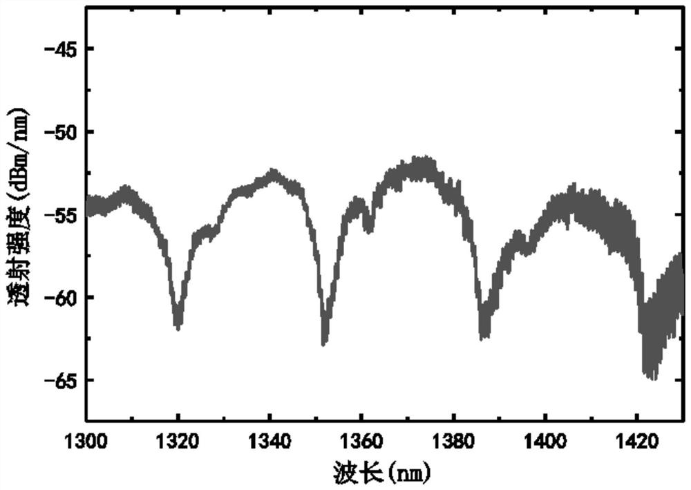
[0029] Embodiment 2: The two ends of the capillary glass tube are cascaded with a convex tapered optical fiber fused from a single-mode optical fiber, and an input optical fiber and an output optical fiber are arranged at both ends of the hybrid structure. The inner diameter of the capillary glass tube is 75 μm, the outer diameter is 125 μm, and the selected length is 5 mm. The single-mode fiber used is a standard single-mode fiber. When the temperature and curvature of the detection area change, the characteristic transmission peak in the cascade spectrum changes. The position and intensity will change. After analyzing the position and intensity of the fine spectral fringes collected by the spectrometer and fast Fourier filtering, the changes in the wavelength and intensity of the anti-resonance transmission peak of the capillary glass tube are detected and specific Signal processing can realize the detection of temperature and curvature changes.

Embodiment 3

[0030] Embodiment 3: The preparation method of the hybrid structure optical fiber sensor based on hollow-core optical fiber cascaded fused cone single-mode optical fiber, comprises the following steps:

[0031] S1. Single-mode optical fiber pretreatment: select two single-mode optical fibers with an inner diameter of 8 μm and an outer diameter of 125 μm, use fiber strippers or blades to remove the coating protective layer of the optical fiber, and wipe the surface of the optical fiber with alcohol to remove its residue ; Use a fiber cleaver to cut one end of the fiber flat.

[0032] S2. Production of convex tapered optical fiber: Use an optical fiber fusion splicer to fuse two single-mode optical fibers processed by S1 together; set the fusion splicing parameters of the optical fiber fusion splicer as follows: use fiber core alignment, overlap 150 μm, and discharge intensity Standard intensity, the discharge time is 2000ms, the second discharge intensity is the standard intens...


PUM

PropertyMeasurementUnit
lengthaaaaaaaaaa
lengthaaaaaaaaaa
lengthaaaaaaaaaa

Abstract

The invention discloses an optical fiber sensor based on a hybrid cascade structure and a preparation method. The optical fiber sensor comprises a capillary glass tube, a single-mode optical fiber with a fused taper, an input optical fiber and an output optical fiber, wherein the input optical fiber and the output optical fiber are arranged at two ends; the input end of the sensing head is connected with the light source, the output end is connected with the spectrograph, and the input and output optical fibers are single-mode optical fibers; and the capillary glass tube is cascaded and weldedbetween the two cones through a welding machine. When the environment temperature of a detection area changes within 25-95 DEG C and the curvature changes within 8.14-9.77 m < -1 > and 10.26-11.6 m <-1 >, the position and the intensity of a characteristic transmission peak in a cascade spectrum can change, and the change of the wavelength and the intensity of the transmission peak is detected after fast Fourier filtering is carried out on the spectrum collected by a spectrograph, so that the temperature and curvature change is detected. The optical fiber sensor is small in size, high in integration level, simple and compact in structure and high in corrosion resistance and electromagnetic interference resistance.

Description

technical field [0001] The invention belongs to the technical field of optical fiber sensor production, and in particular relates to an optical fiber sensor based on a hybrid cascade structure and a preparation method. Background technique [0002] Temperature and curvature measurement covers a wide range of fields, such as health detection of building structures, environmental monitoring of various military and civilian industries such as machinery industry and aerospace. There are many kinds of temperature and curvature sensors commonly used at present, including traditional electrical sensors, such as piezoelectric electrical devices, etc.; new optical sensors, mainly fiber Bragg grating type, fiber optic long period grating type, etc. However, the detection range and sensitivity of traditional electrical sensors are limited due to their design structure and the characteristics of materials used. In addition, in a complex use environment, it is susceptible to interferenc...

Claims


Application Information

Patent Timeline
Patent Type & Authority Applications(China)
IPC IPC(8): G01K11/32G01B11/24
CPCG01B11/2441G01K11/32
Inventor 吴舜程海皓王顺王强
Owner WUHAN INSTITUTE OF TECHNOLOGY
Learn More