
Tool placing rack for constructional engineering

A technology of construction engineering and placing racks, which is applied in the field of racks, can solve problems such as leveling quality doubts, inability to bring convenience, inability to flexibly adjust, etc., and achieve the effect of quality assurance

Inactive Publication Date: 2020-12-08
江苏杭鼎建设工程有限公司
View PDF0 Cites 0 Cited by
  • Summary
  • Abstract
  • Description
  • Claims
  • Application Information

AI Technical Summary

Problems solved by technology

[0002] The storage rack is a shelf combined with a bottom plate and a pillar to store sundries. It is mostly supported by strip brackets and supported by the bottom plate. It can be seen that the height of the pallets of the early storage racks is not adjustable, and is always fixed at a height, which cannot be adjusted flexibly, and thus cannot effectively bring convenience to the working environment, and the pallets used in the early storage racks adopt It’s just an ordinary iron plate, its quality can’t bear the weight of long-term placed objects to cause deformation, especially in construction, the weight of some tools must exceed ordinary tools, and the early storage racks did not have any protection measures, the same If a heavy object falls on the building site and hits the shelf, then the shelf will be directly damaged, making the quality of the leveling questionable. When the existing shelf is installed and used, it brings certain problems to people's use Adverse effects, for this reason, we propose a tool placement rack for construction engineering

Method used


Image

  • Tool placing rack for constructional engineering
  • Tool placing rack for constructional engineering
  • Tool placing rack for constructional engineering

Examples


Embodiment Construction

[0023] In order to make the technical means, creative features, goals and effects achieved by the present invention easy to understand, the present invention will be further described below in conjunction with specific embodiments.

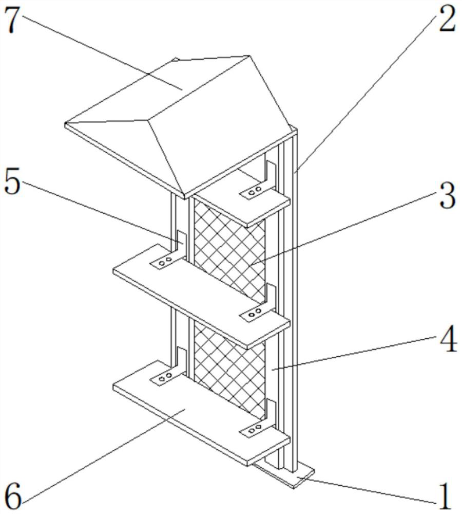
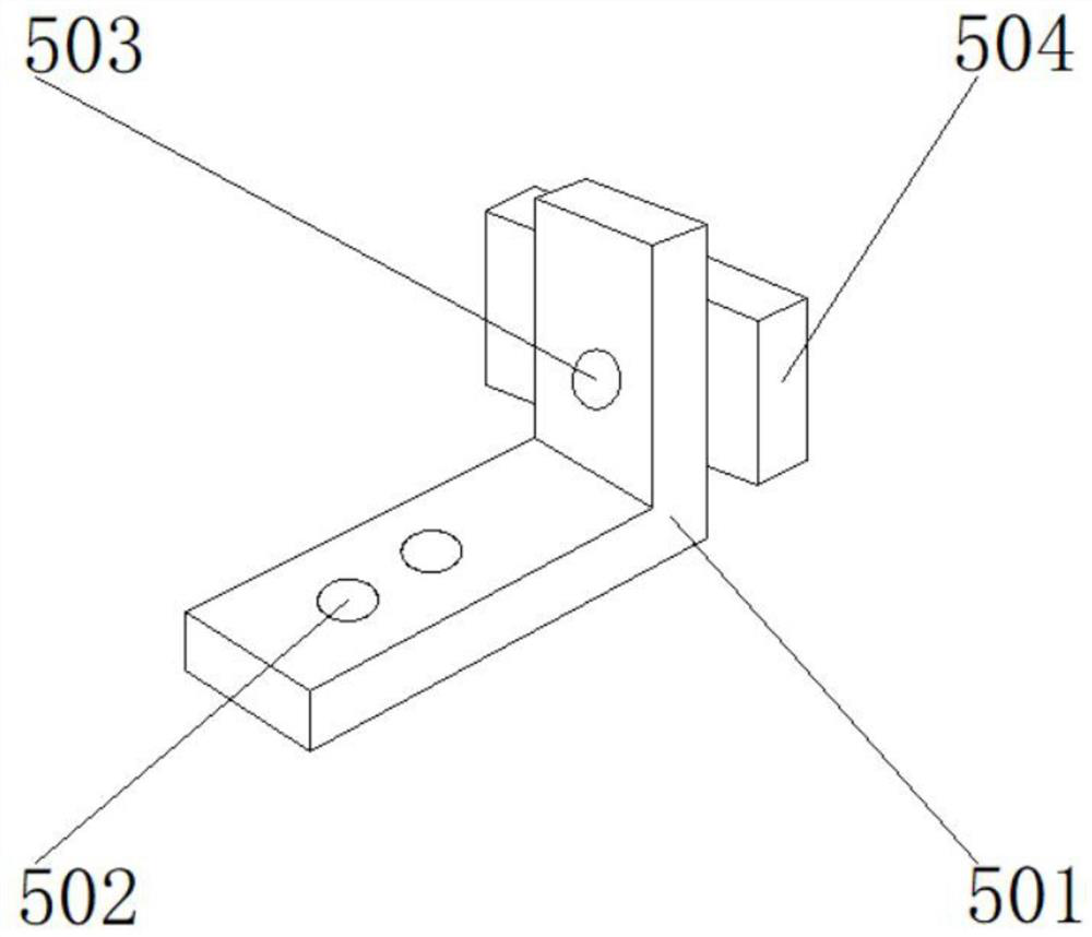
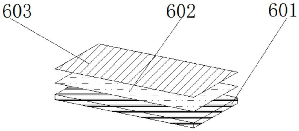
[0024] Such as Figure 1-4 Shown, a kind of tool placement rack for construction engineering, the outer surface of the upper end of the main body 1 is provided with a casing 2, one side of the inner wall of the casing 2 is provided with a protective net 3, the outer surface of the front end of the casing 2 is provided with a lifting rail 4, the lifting rail 4 The outer surface of the front end is provided with a movable fixed block 5, the outer surface of the front end of the movable fixed block 5 is provided with a high-strength supporting plate 6, the outer surface of the upper end of the casing 2 is provided with a protective plate 7, and the movable fixed block 5 includes a movable block 501 and a screw hole 502 , positioning holes 503 and sli...


PUM


Abstract

The invention discloses a tool placing rack for constructional engineering. A casing is arranged on the outer surface of the upper end of a main body; a protective net is arranged on one side of the inner wall of the casing; a lifting rail is arranged on the outer surface of the front end of the casing; a movable fixing block is arranged on the outer surface of the front end of the lifting rail; ahigh-strength supporting plate is arranged on the outer surface of the front end of the movable fixing block; a protective plate is arranged on the outer surface of the upper end of the casing; the movable fixing block comprises a movable block, a screw hole, a positioning hole and a sliding block; and the high-strength supporting plate comprises an oak plate, varnish and a protective film. According to the tool placing rack for constructional engineering, the height of the supporting plate can be adjusted at will through the sliding block adopted by the movable fixing block, and the supporting plate is fixed through the positioning hole after being adjusted, so that the product has certain flexibility, then convenience is effectively brought to work, and the tool placing rack for constructional engineering has a better using prospect.

Description

technical field [0001] The invention relates to the field of racks, in particular to a tool rack for construction engineering. Background technique [0002] The storage rack is a shelf combined with a bottom plate and a pillar to store sundries. It is mostly supported by strip brackets and supported by the bottom plate. It can be seen that the height of the pallets of the early storage racks is not adjustable, and is always fixed at a height, which cannot be adjusted flexibly, and thus cannot effectively bring convenience to the working environment, and the pallets used in the early storage racks adopt It’s just an ordinary iron plate, its quality can’t bear the weight of long-term placed objects to cause deformation, especially in construction, the weight of some tools must exceed ordinary tools, and the early storage racks did not have any protection measures, the same If a heavy object falls on the building site and hits the shelf, then the shelf will be directly damaged...

Claims


Application Information

Patent Timeline
IPC IPC(8): B25H3/04
CPCB25H3/04
Inventor 杨寅丁卫东张清玉曹仁安
Owner 江苏杭鼎建设工程有限公司
Learn More