
Method for calcining and deeply desulfurizing electrolytic aluminum prebaked anode

A prebaked anode and deep desulfurization technology, which is applied in separation methods, chemical instruments and methods, and process efficiency improvement, can solve the problems of flue gas waste, high waste heat of flue gas and difficult desulfurization tower desulfurization, etc., to ensure desulfurization effect, The effect of reducing the total amount of SO2 and dust and avoiding adverse effects

Active Publication Date: 2020-12-08
百色皓海碳素有限公司
View PDF7 Cites 0 Cited by
  • Summary
  • Abstract
  • Description
  • Claims
  • Application Information

AI Technical Summary

Problems solved by technology

[0003] In the existing desulfurization method, the flue gas is directly passed into the desulfurization tower for desulfurization treatment. On the one hand, a large amount of waste heat in the flue gas cannot be effectively utilized, resulting in waste; desulfurization

Method used


Image

  • Method for calcining and deeply desulfurizing electrolytic aluminum prebaked anode
  • Method for calcining and deeply desulfurizing electrolytic aluminum prebaked anode
  • Method for calcining and deeply desulfurizing electrolytic aluminum prebaked anode

Examples


Embodiment 1

[0036] A method for deep desulfurization of electrolytic aluminum prebaked anode calcining, comprising:

[0037] The original high-temperature flue gas produced by the calciner of the calciner is introduced into the waste heat power generation boiler system through the flue gas recovery pipeline system; in the power generation boiler system, the flue gas drives the waste heat generator set to generate electricity through the steam generated by the waste heat boiler; The flue gas is introduced into the desulfurization tower for desulfurization and dust reduction.

[0038] In the above scheme, the waste heat in the flue gas produced by the calciner is introduced into the waste heat boiler to be heated to generate steam for power generation, so that the waste heat of the flue gas can be effectively utilized. The adverse effect of high temperature flue gas on desulfurization ensures the desulfurization effect.

Embodiment 2

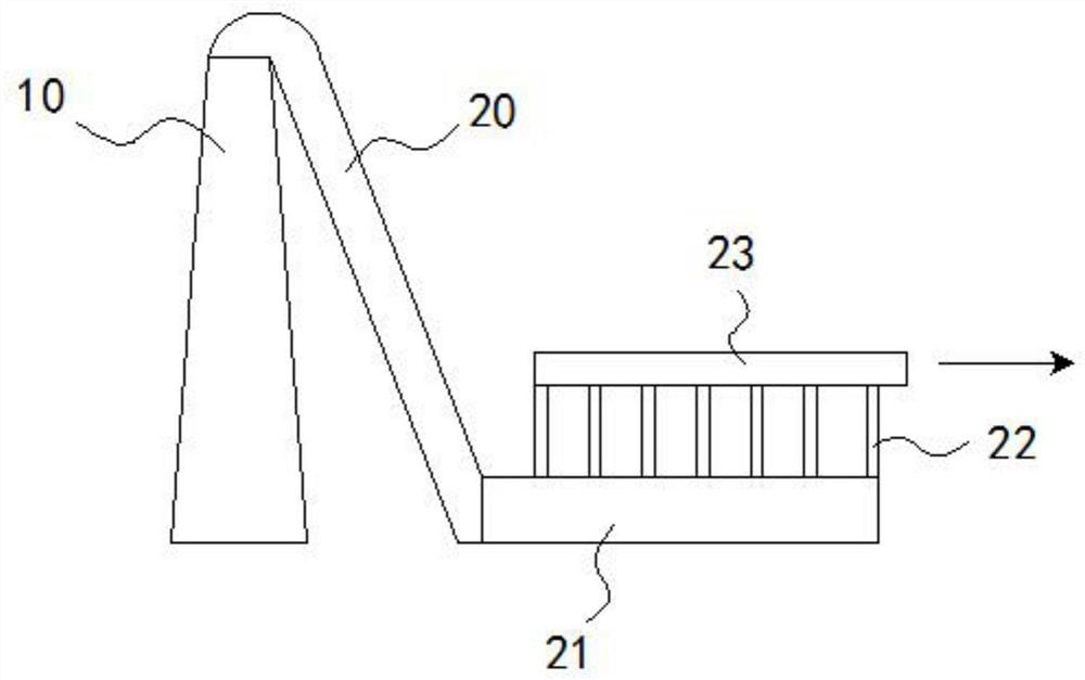
[0040] Such as figure 1 As shown, on the basis of Example 1, flue gas is collected in the chimney 10 of the calcination plant, and the chimney 10 is provided with a flue gas inlet and a flue gas outlet, the flue gas inlet is communicated with the calciner, and the flue gas outlet is connected with the flue gas recovery Piping system connected.

[0041] The flue gas recovery pipeline system includes:

[0042] A descending section 20, which extends obliquely downward from the top of the chimney 10 to the ground; the descending section 20 communicates with the chimney 10 to introduce flue gas;

[0043] A settling section 21, which communicates with the descending section 20 and extends horizontally along the ground; the inner diameter of the settling section 21 is larger than the inner diameter of the descending section 20 so that the smoke slows down;

[0044] A plurality of vertical pipes 22, which are vertically arranged above the settling section 21 and communicate with the...

Embodiment 3

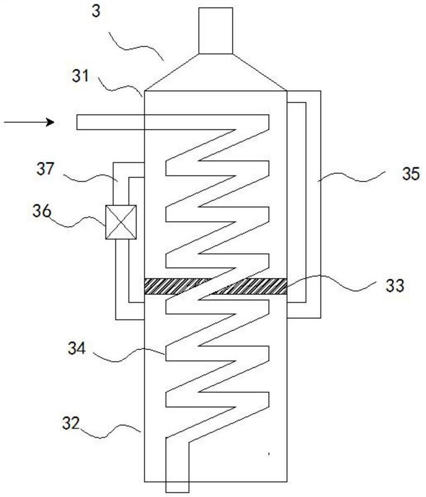
[0048] Such as figure 2 As shown, on the basis of Example 2, the waste heat boiler 3 includes an upper drum 31, a lower drum 32 and a convection tube bundle 34, the convection tube bundle 34 is connected to the flue gas discharge port to introduce flue gas, and the convection tube bundle 34 The tube bundle 34 first passes through the inside of the upper drum 31 and then through the inside of the lower drum 32 to first heat the water in the upper drum 31 and then heat the water in the lower drum 32 .

[0049]The upper drum 31 and the lower drum 32 are separated by a partition 33 to form two heating spaces, and the convection tube bundle 34 spirals downward from the center of the upper drum 31 and enters the lower drum 32 through the partition 33 . The side wall of the lower drum 32 is provided with a gas pipe 35 connected to the upper drum 31 to discharge steam into the upper drum 31, and the outer wall of the lower drum 32 is also provided with a water pump 36, and the water ...


PUM


Abstract

The invention discloses a method for calcining and deeply desulfurizing an electrolytic aluminum prebaked anode. The method comprises the following steps: original high-temperature flue gas generatedby a calcining furnace of a calcining plant is introducedinto a waste heat power generation boiler system through a flue gas recovery pipeline system; the flue gas drives a waste heat generator set togenerate electricity through steam generated by a waste heat boiler; and the flue gas cooled by the waste heat boiler is introduced into a desulfurization tower for desulfurization and dust reduction. Waste heat in the flue gas generated by the calcining furnace is introduced into the waste heat boiler to be heated to generate the steam for power generation, so that the flue gas waste heat is effectively utilized, meanwhile, the flue gas is introduced into the desulfurization tower for desulfurization after being cooled through power generation, the adverse effect of high-temperature flue gason desulfurization is avoided, and the desulfurization effect is guaranteed. After desulfurization and dust removal by using the method disclosed by the invention, pollutants meet the emission standard, the content of sulfur dioxide is less than 35mg / Nm < 3 >, the content of smoke dust is less than 10mg / Nm < 3 >, and the content of reference oxygen is 15%; the total amount of SO2 and dust discharged from a chimney of the calcining plant is greatly reduced, and the aim of meeting the national emission specified value or above is achieved.

Description

technical field [0001] The invention relates to the technical field of electrolytic aluminum flue gas treatment, more specifically, the invention relates to a method for deep desulfurization of electrolytic aluminum prebaked anode calcining. Background technique [0002] During the calcination process of electrolytic aluminum prebaked anodes, a large amount of flue gas will be generated. These flue gases contain sulfur dioxide and other polluting gases. If they are not handled properly or directly discharged into the air, they will cause serious pollution. Therefore, flue gas desulfurization treatment is required. [0003] In the existing desulfurization method, the flue gas is directly passed into the desulfurization tower for desulfurization treatment. On the one hand, a large amount of waste heat in the flue gas cannot be effectively utilized, resulting in waste; desulfurization. [0004] Therefore, it is urgent to design a method for deep desulfurization of electrolytic...

Claims


Application Information

Patent Timeline
IPC IPC(8): B01D53/80B01D53/50B03C3/16F01D15/10F01K11/02
CPCB01D53/80B01D53/50B03C3/16F01K11/02F01D15/10B01D2258/0283Y02P10/25
Inventor 黄龙杨洪保黄三财徐赋曹建富巫桂萍刘胜园陈朝永罗军建陈太锋黄振友谭德钱曾福祥陆剑黄望
Owner 百色皓海碳素有限公司
Learn More