A kind of thin film piezoelectric acoustic wave filter and its manufacturing method

A piezoelectric sound wave and manufacturing method technology, applied in the direction of electrical components, impedance networks, etc., can solve the problems of the material of the sealing layer entering the cavity and low reliability, and achieve good control, increased flexibility, and balanced support strength required effect

Active Publication Date: 2022-08-05
NINGBO SEMICON INT CORP
View PDF6 Cites 0 Cited by
  • Summary
  • Abstract
  • Description
  • Claims
  • Application Information

AI Technical Summary

Problems solved by technology

[0007] The technical problem to be solved by the present invention is: the packaging process reliability of the upper cavity formed by the thin-film piezoelectric acoustic wave filter in the prior art is low, and the material of the sealing layer enters the cavity

Method used


Image

  • A kind of thin film piezoelectric acoustic wave filter and its manufacturing method
  • A kind of thin film piezoelectric acoustic wave filter and its manufacturing method
  • A kind of thin film piezoelectric acoustic wave filter and its manufacturing method

Examples


Embodiment 1

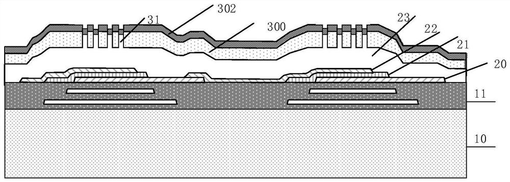
[0036] An embodiment of the present invention provides a thin-film piezoelectric acoustic wave filter, figure 1It is a schematic structural diagram of a thin-film piezoelectric acoustic wave filter according to an embodiment of the present invention, wherein only two acoustic wave resonator units are shown in the figure, and the specific number of acoustic wave resonator units in each filter and the electrical connection between them are shown. The mode is specifically set according to the requirements of the filter itself.

[0037] Please refer to figure 1 , the thin-film piezoelectric acoustic wave filter includes:

[0038] a first substrate; a plurality of acoustic wave resonator units placed on the first substrate; the acoustic wave resonator unit is the smallest resonance unit, and each acoustic wave resonator unit includes a piezoelectric induction sheet 21 for resonating the The piezoelectric induction sheet body 21 applies a voltage to the first electrode and the sec...

Embodiment 2

[0053] This embodiment provides a method for manufacturing a thin-film piezoelectric acoustic wave filter, the method comprising:

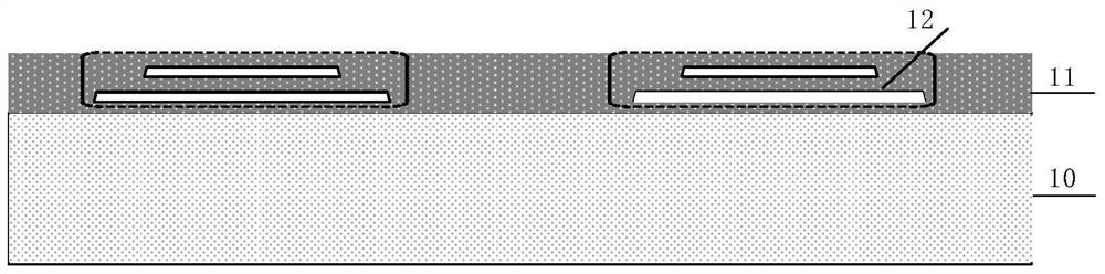
[0054] S01: provide a first substrate;

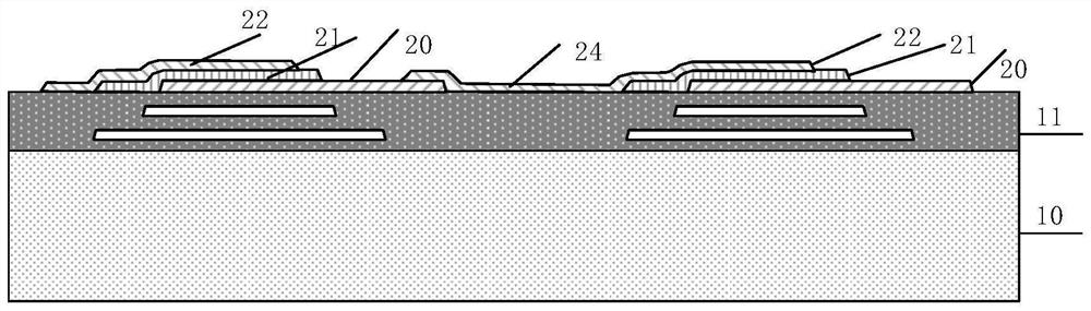
[0055] S02: forming a plurality of acoustic wave resonator units on the first substrate, each acoustic wave resonator unit including a piezoelectric induction sheet body and first electrodes opposite to each other for applying a voltage to the piezoelectric induction sheet body , the second electrode;

[0056] S03: forming a sacrificial layer on at least two of the acoustic wave resonator units and the spaced area between the acoustic wave resonator units;

[0057] S04: forming a cap layer body, covering the sacrificial layer, forming a release hole with a set aperture on the cap layer body, and removing the sacrificial layer through the release hole to form a first cavity;

[0058]S05: Form a capping layer on the capping layer body, so that the capping layer is partially embedded in a part of the release...


PUM


Abstract

The invention discloses a thin-film piezoelectric acoustic wave filter and a manufacturing method thereof, wherein the thin-film piezoelectric acoustic wave filter comprises: a first substrate; a plurality of acoustic wave resonator units placed on the first substrate, each of the The acoustic wave resonator unit includes a piezoelectric induction sheet body, a first electrode and a second electrode opposite to each other for applying a voltage to the piezoelectric induction sheet body; a cap layer on the first substrate, the cap The layer surrounds at least two of the acoustic wave resonator units to form a first cavity between the acoustic wave resonator units and the capping layer; the capping layer includes: a capping layer body having a release hole with a set aperture , and a cover layer that seals the release hole, and a part of the cover layer is embedded in a part of the release hole. The invention can solve the problem that the packaging process of the upper cavity has low reliability and the material of the capping layer enters the cavity.

Description

technical field [0001] The invention relates to the field of semiconductor device manufacturing, in particular to a thin-film piezoelectric acoustic wave filter and a manufacturing method thereof. Background technique [0002] With the development of wireless communication technology, traditional single-band and single-standard equipment can no longer meet the diversified requirements of communication systems. At present, the communication system is becoming more and more multi-frequency band, which requires that the communication terminal can accept various frequency bands to meet the requirements of different communication service providers and different regions. [0003] RF (radio frequency) filters are typically used to pass or block specific frequencies or frequency bands in RF signals. In order to meet the development needs of wireless communication technology, it is required that the RF filters used in communication terminals can meet the technical requirements of mu...

Claims


Application Information

Patent Timeline
Patent Type & Authority Patents(China)
IPC IPC(8): H03H9/64
CPCH03H9/64
Inventor 黄河罗海龙李伟
Owner NINGBO SEMICON INT CORP
Why Eureka
Try Eureka