A preparation device and method for directional steel fiber reinforced concrete prefabricated components
A technology for reinforcing concrete and prefabricated components, applied in the direction of manufacturing tools, ceramic molding machines, etc., can solve the problems of insufficient tensile strength of concrete matrix and low efficiency of one-way reinforcement, and achieve the effect of flexible cross-sectional form of components and improved structural mechanical properties
- Summary
- Abstract
- Description
- Claims
- Application Information
AI Technical Summary
Problems solved by technology
Method used
Image
Examples
Embodiment
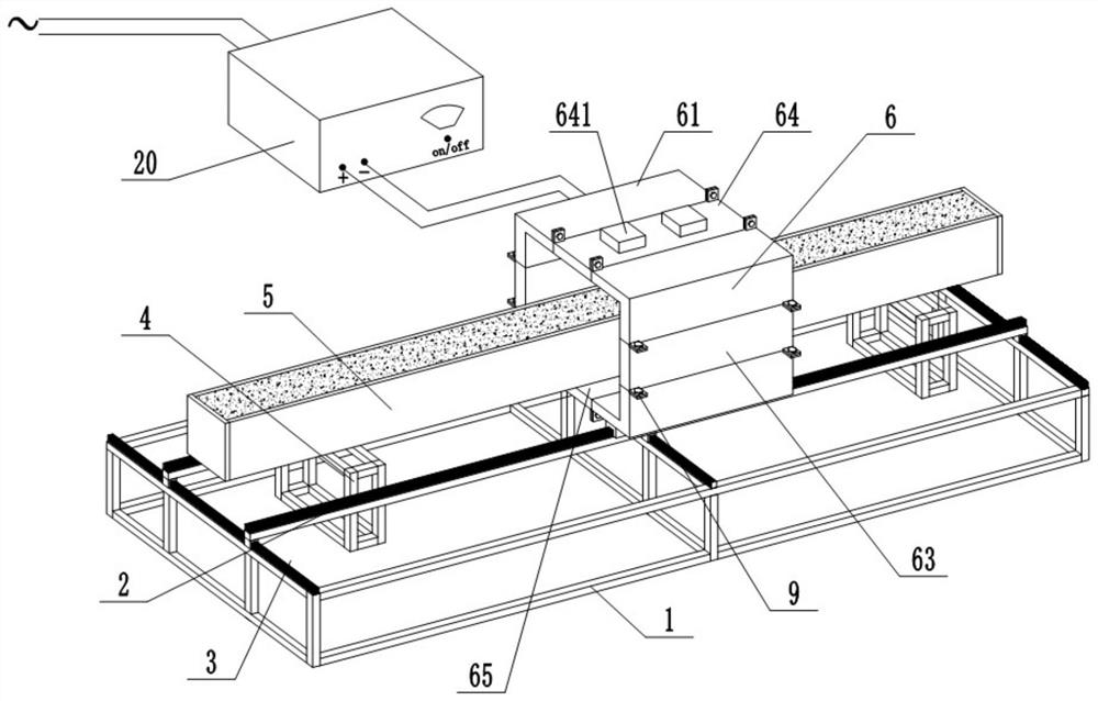
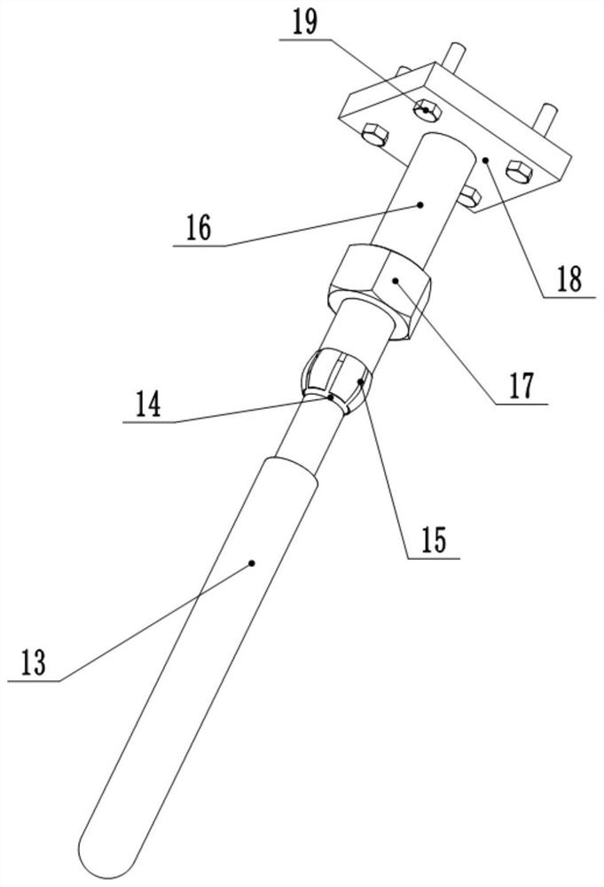
[0035] like figure 1 , figure 2 , image 3 , Figure 4 , Figure 5 , Image 6 , Figure 7 , Figure 8 , Figure 9 and Figure 10 shown:
[0036]An oriented steel fiber reinforced concrete prefabricated component preparation device, comprising a support frame 1 at the bottom, the support frame 1 is a rectangular metal frame, and the upper surface of the support frame 1 is provided with two first slide rails 2 in the horizontal direction, and two first slide rails 2 in the horizontal direction. A slide rail 2 is symmetrically arranged; the first slide rail 2 is provided with a coil 6, the bottom of the coil 6 is fixed with a pulley 12, the coil 6 is slidably connected to the first slide rail 2 through the pulley 12, and the support frame 1 is fixed with a second The slide rail 3, the second slide rail 3 is perpendicular to the first slide rail 2, and the first slide rail 2 is slidably connected to the second slide rail 3; the bottom of the support frame 1 is placed wit...
specific Embodiment approach
[0037] A method for preparing an oriented steel fiber reinforced concrete prefabricated member, using the above-mentioned device for preparing an oriented steel fiber reinforced concrete prefabricated member, comprising the following steps:
[0038] The first step: install the coil 6; according to the size of the non-metallic template 5, adjust the number of the air inlet module 64, the air outlet module 65 and the flat plate module 63, and assemble the coil 6 through the bolt 19 and the splicing plate 9; The vibrating rod 13 is installed on the lower surface of the air inlet module 64. After rotating the vibrating rod 13 to the desired angle, rotate the nut 17 downward, the nut 17 presses the shrapnel 15, and the shrapnel 15 fixes the vibrating rod 13; slide The first slide rail 2, so that the first slide rail 2 is respectively facing the pulley 12, then the coil 6 is placed on the first slide rail 2, the port is connected with the current exchanger 20, and the installation of...
PUM
 Abstract
Description
Claims
Application Information
 - R&D
- Intellectual Property
- Life Sciences
- Materials
- Tech Scout
- Unparalleled Data Quality
- Higher Quality Content
- 60% Fewer Hallucinations
Browse by: Latest US Patents, China's latest patents, Technical Efficacy Thesaurus, Application Domain, Technology Topic, Popular Technical Reports.
© 2025 PatSnap. All rights reserved.Legal|Privacy policy|Modern Slavery Act Transparency Statement|Sitemap|About US| Contact US: help@patsnap.com


