
Tray steel pipe embedding machine

A technology of steel pipes and pallets, which is applied in the field of pallet steel pipe embedding machines, can solve problems such as hammers easily hitting people's hands, operator safety accidents, and hammers easily hitting pallets, etc., so as to avoid displacement, move smoothly, Avoid the effect of surface abrasion

Inactive Publication Date: 2020-12-04
孙惠珍
View PDF6 Cites 2 Cited by
  • Summary
  • Abstract
  • Description
  • Claims
  • Application Information

AI Technical Summary

Problems solved by technology

[0006] In order to overcome the disadvantages that it is difficult for people to accurately hammer the hammer on the steel pipe, the hammer is easy to hit people's hands, causing safety accidents for operators, and the hammer is easy to hit the pallet, resulting in damage to the pallet. The technical problem to be solved by the invention is to provide a pallet steel pipe embedding machine that can accurately hammer the steel pipe into the pallet, avoiding the hammer from hitting people's hands and the pallet, and protecting the safety of the operator and the pallet.

Method used


Image

  • Tray steel pipe embedding machine
  • Tray steel pipe embedding machine
  • Tray steel pipe embedding machine

Examples


Embodiment 1

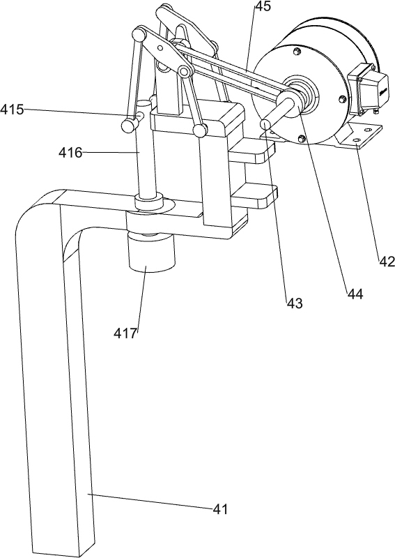
[0027] A pallet steel pipe embedding machine, such as Figure 1-5 As shown, it includes a base 1, a first baffle 2, a pillar 3, a transmission mechanism 4 and an embedded mechanism. The left front and right rear sides of the top of the base 1 are connected to the first baffle 2, and the middle part of the right side of the base 1 is connected to There is a pillar 3, a transmission mechanism 4 is installed between the pillar 3 and the base 1, and an embedded mechanism is installed on the transmission mechanism 4.

[0028] The transmission mechanism 4 includes a first support 41, a motor 42, a first transmission shaft 43, a first pulley 44, a first flat belt 45, a second transmission shaft 46 and a second pulley 47, and the left middle part of the base 1 is equipped with the first A bracket 41, the first bracket 41 is connected with the pillar 3, the top rear side of the pillar 3 is connected with a motor 42, the output shaft of the motor 42 is connected with a first transmissio...

Embodiment 2

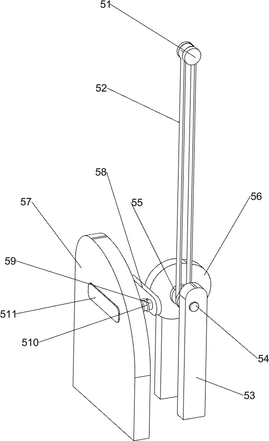
[0032] On the basis of Example 1, such as Figure 6 As shown, a clamping mechanism 5 is also included, and the clamping mechanism 5 includes a third pulley 51, a second flat belt 52, a second bracket 53, a third transmission shaft 54, a fourth pulley 55, a cam 56, a second gear Plate 57, transmission block 58, movable bar 59, spring 510 and pressure block 511, the front end of the first transmission shaft 43 is fixedly connected with the 3rd pulley 51, and the right side of base 1 top is equipped with the second support 53, and the second support 53 tops Rotationally connected with the third transmission shaft 54, the third transmission shaft 54 ​​is fixedly connected with the fourth pulley 55, the second flat belt 52 is connected between the fourth pulley 55 and the third pulley 51, the third transmission shaft 54 The rear part is connected with a cam 56, and the right side of the base 1 is provided with a second baffle plate 57, the second baffle plate 57 is located between ...

Embodiment 3

[0035] On the basis of Example 2, such as Figure 7 As shown, also includes conveying mechanism 6, and conveying mechanism 6 comprises conveying plate 61, wheel connecting shaft 62 and transport wheel 63, has groove in the middle of base 1 top, is provided with conveying plate 61 slidingly in the groove, conveys The front and rear sides of the bottom of the plate 61 are rotatably connected with a wheel connecting shaft 62, and the left and right ends of the wheel connecting shaft 62 are connected with transport wheels 63, and the transport wheels 63 contact with the inner bottom of the groove.

[0036] Pallet is placed vertically on conveying plate 61, people pushes on conveying plate 61 and moves backward, can make moving conveying plate 61 move more smoothly by transport wheel 63, can also avoid the surface wear that pallet causes when moving on the base plate.


PUM


Abstract

The invention relates to an embedding machine, in particular to a tray steel pipe embedding machine. According to the tray steel pipe embedding machine, the technical problem to be solved is to provide the tray steel pipe embedding machine capable of accurately hammering a steel pipe into a tray, preventing an iron hammer from hammering the hands of people and the tray and protecting the safety ofoperators and the tray. In order to solve the technical problem, the invention provides the tray steel pipe embedding machine, and the tray steel pipe embedding machine comprises a base, a strut, a transmission mechanism and an embedding mechanism, wherein a first baffle plate is arranged at the top of the base; the strut is connected to the middle part of one side of the base; the transmission mechanism is mounted between the strut and the base; and the embedding mechanism is mounted on the transmission mechanism. Through cooperation of the transmission mechanism and the embedding mechanism,the steel pipe can be rapidly extruded into an embedding groove of the tray, so that the working efficiency is improved, people do not need to hammer the steel pipe with the iron hammer, and the trayis prevented from being damaged.

Description

technical field [0001] The invention relates to an embedding machine, in particular to a tray steel pipe embedding machine. Background technique [0002] Pallet is a medium that transforms static goods into dynamic goods, a kind of loading platform, and it is an active platform, or a movable ground. Even the goods that lose their flexibility on the ground will immediately gain mobility as soon as they are loaded on the pallet and become flexible flow goods, because the goods on the pallet are in a state of being ready to move at any time. This dynamic loading and unloading method composed of pallets as the basic tool is called pallet operation. [0003] Pallets need to be embedded in steel pipes during production. The purpose is to improve the rigidity of the pallets and thus extend the service life of the pallets. At present, the way pallets are embedded in steel pipes is usually to place the pallets on the ground. People hold the hammer in one hand and the other Insert t...

Claims


Application Information

Patent Timeline
Patent Type & Authority Applications(China)
IPC IPC(8): B23P19/00B23P19/02B65D19/38
CPCB23P19/001B23P19/02B65D19/38
Inventor 孙惠珍
Owner 孙惠珍
Learn More