
Covered stent

A technology of covered stent and film, which is applied in the field of medical devices, can solve the problem of low safety of carotid artery stent, and achieve the effect of good safety in use

Pending Publication Date: 2020-12-04
SUZHOU ZENITH VASCULAR SCITECH LTD
View PDF0 Cites 0 Cited by
  • Summary
  • Abstract
  • Description
  • Claims
  • Application Information

AI Technical Summary

Problems solved by technology

[0009] The purpose of the present invention is to provide a covered stent to solve the problem of lower safety of the existing carotid stent

Method used


Image

  • Covered stent
  • Covered stent
  • Covered stent

Examples


Embodiment 1

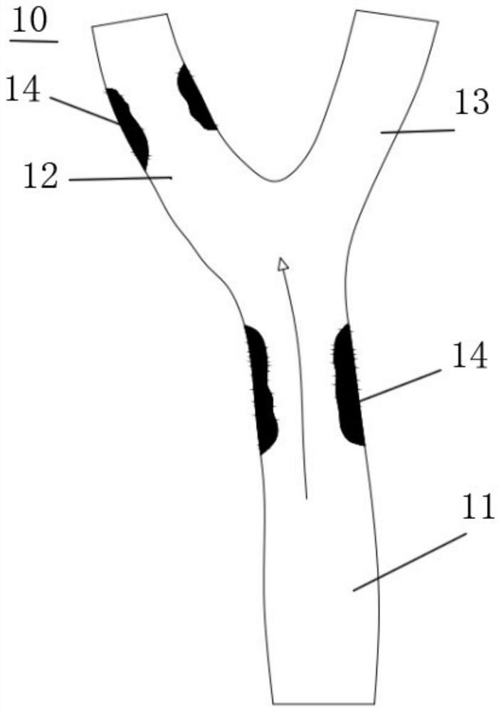
[0042] figure 1 It is a structural diagram of the carotid artery 10 of the embodiment of the present invention. Such as figure 1 As shown, the carotid artery 10 is divided into a common carotid artery 11 , an internal carotid artery 12 and an external carotid artery 13 , and the common carotid artery 11 , the internal carotid artery 12 and the external carotid artery 13 form a Y-shaped bifurcation structure. The blood of the common carotid artery 11 flows into the internal carotid artery 12 and the external carotid artery 13 respectively at the Y-shaped bifurcation structure. Among them, the blood of the internal carotid artery 12 mainly flows to the brain, and the blood of the external carotid artery 13 mainly supplies the facial organs. There are plaques 14 on the common carotid artery 11 and the internal carotid artery 12, and the plaques 14 lead to narrowing of blood vessels and affect blood flow. Therefore, it is necessary to install a covered stent at the lesion to su...

Embodiment 2

[0062] This embodiment is basically the same as Embodiment 1, except that the film 22 in Embodiment 1 has a single-layer structure, while the film 22 in this embodiment has a double-layer structure.

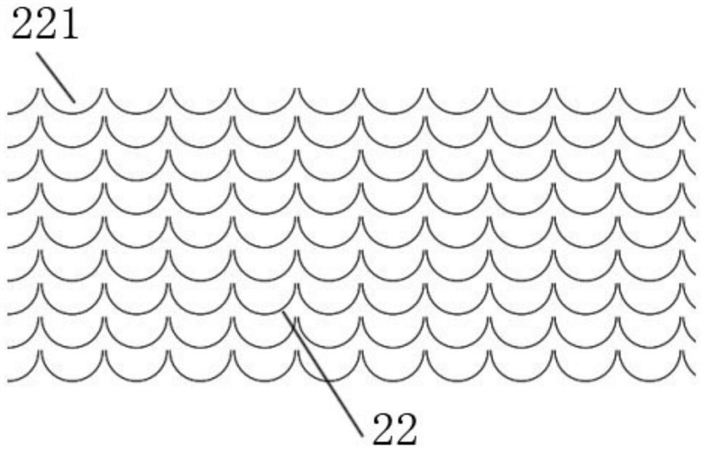
[0063] Figure 6 It is a structural diagram of the two-layer film 22 of the stent graft 20 according to the embodiment of the present invention. Such as Figure 6 As shown, preferably, there is an overlapping area 222 between the openings 221 of the two films 22 . Specifically, each opening 221 of each film 22 has a semicircular structure, and multiple groups of openings 221 form a scale-like structure as a whole.

[0064] Preferably, the closed end of the opening 221 of the outer film 22 is laminated to the open end of the opening 221 of the inner film 22 . The open end of the opening 221 refers to the open end of the figure surrounded by the outline of the opening 221 , and the closed end of the opening 221 refers to the closed end of the figure surrounded by the outline of ...


PUM


Abstract

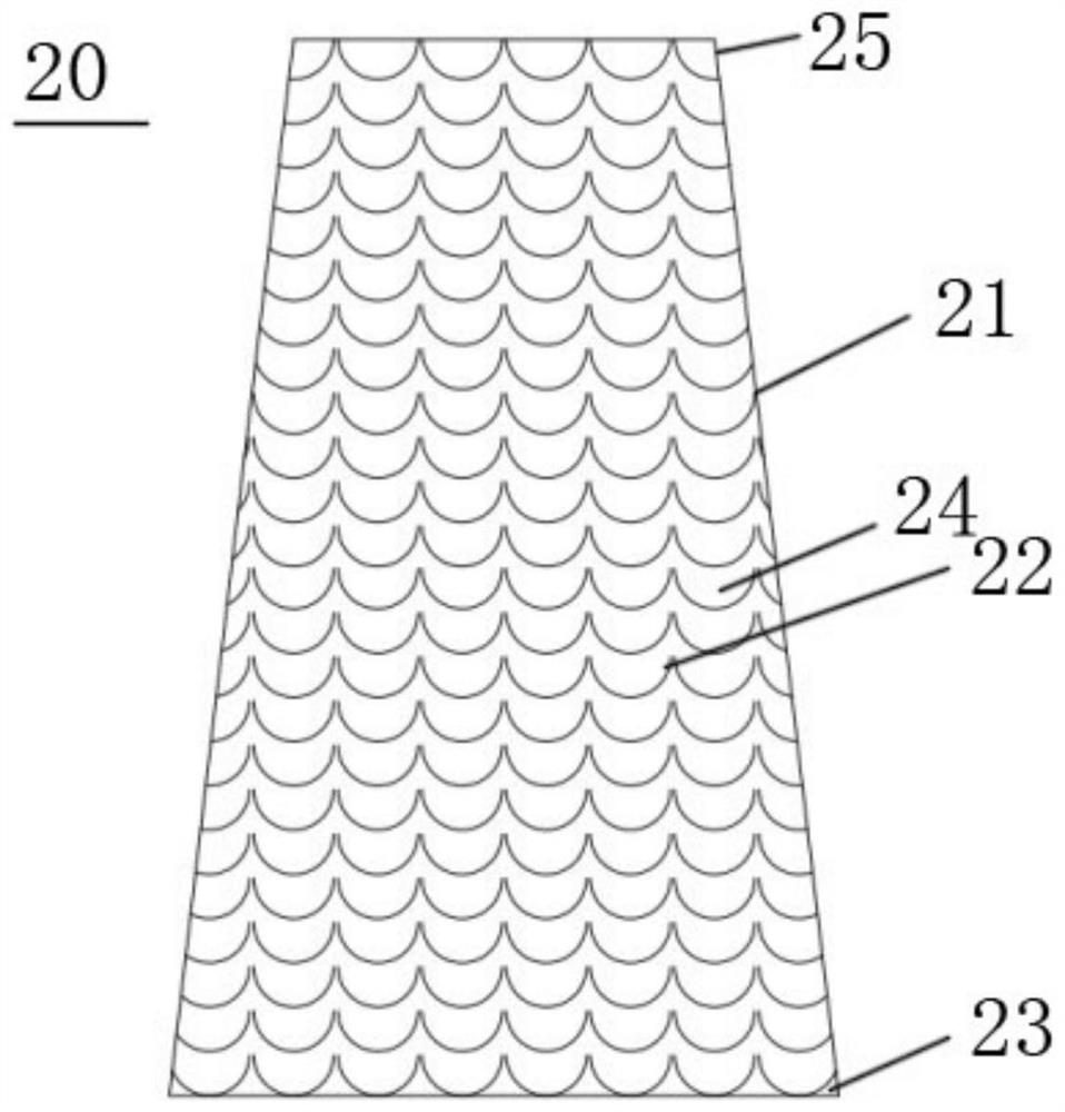
The invention belongs to the technical field of medical instruments, and particularly relates to a covered stent. The covered stent includes a stent body and a thin film, wherein the stent body comprises a near end and a far end, and the near end is arranged in the upstream position of a blood vessel relative to the far end. The thin film is installed on and covers the stent body, and a pluralityof openings are formed in the surface of the thin film and face the near end or the far end of the stent body. After the stent body is mounted at a Y-shaped bifurcation of a carotid artery, the stentbody is opened, and the film is opened along with the stent body and covers plaques in the blood vessel, so that the plaques can be prevented from being broken and falling off due to extrusion of thestent body. Besides, after the stent body is installed on the common carotid artery and the internal carotid artery, blood flow entering the external carotid artery from the common carotid artery easily rushes through the thin film located at the entrance of the external carotid artery, and therefore the blood is ensured to normally enter the external carotid artery. In conclusion, the use safetyof the covered stent is better.

Description

technical field [0001] The invention belongs to the technical field of medical devices, and in particular relates to a covered stent. Background technique [0002] Cerebrovascular disease is a major disease that threatens human health today, and is the third leading cause of death after cardiovascular disease and tumors. Among them, 25% of ischemic strokes are related to carotid artery stenosis or occlusion. [0003] The treatment of carotid artery stenosis is mainly divided into drug therapy, carotid endarterectomy, and carotid artery stenting. Among them, carotid artery stenting has the advantages of simple operation, less trauma, and fewer complications, and is currently one of the effective methods for treating carotid artery stenosis. [0004] The carotid artery is divided into the common carotid artery, the external carotid artery and the internal carotid artery. The common carotid artery, the external carotid artery and the internal carotid artery have a Y-shaped bif...

Claims


Application Information

Patent Timeline
Patent Type & Authority Applications(China)
IPC IPC(8): A61F2/07A61F2/06A61F2/90
CPCA61F2/07A61F2/90A61F2002/061
Inventor 李爽汪泽辉夏洁
Owner SUZHOU ZENITH VASCULAR SCITECH LTD
Learn More