
Industrial waste gas heat recovery device

A technology of heat recovery device and industrial waste gas, which is applied in the direction of combined devices, indirect heat exchangers, heat exchange equipment, etc., can solve the problems of energy waste and the inability to recover the heat of industrial waste gas, so as to reduce the speed of ash accumulation, maintain smooth flow, and reduce pollution effect

Pending Publication Date: 2020-12-01
四川陆亨能源科技有限公司
View PDF0 Cites 0 Cited by
  • Summary
  • Abstract
  • Description
  • Claims
  • Application Information

AI Technical Summary

Problems solved by technology

[0004] The purpose of the present invention is to provide an industrial waste gas heat recovery device to solve the problem that the heat in the industrial waste gas cannot be recovered and cause energy waste

Method used


Image

  • Industrial waste gas heat recovery device
  • Industrial waste gas heat recovery device
  • Industrial waste gas heat recovery device

Examples


Embodiment 1

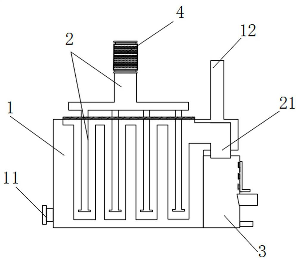
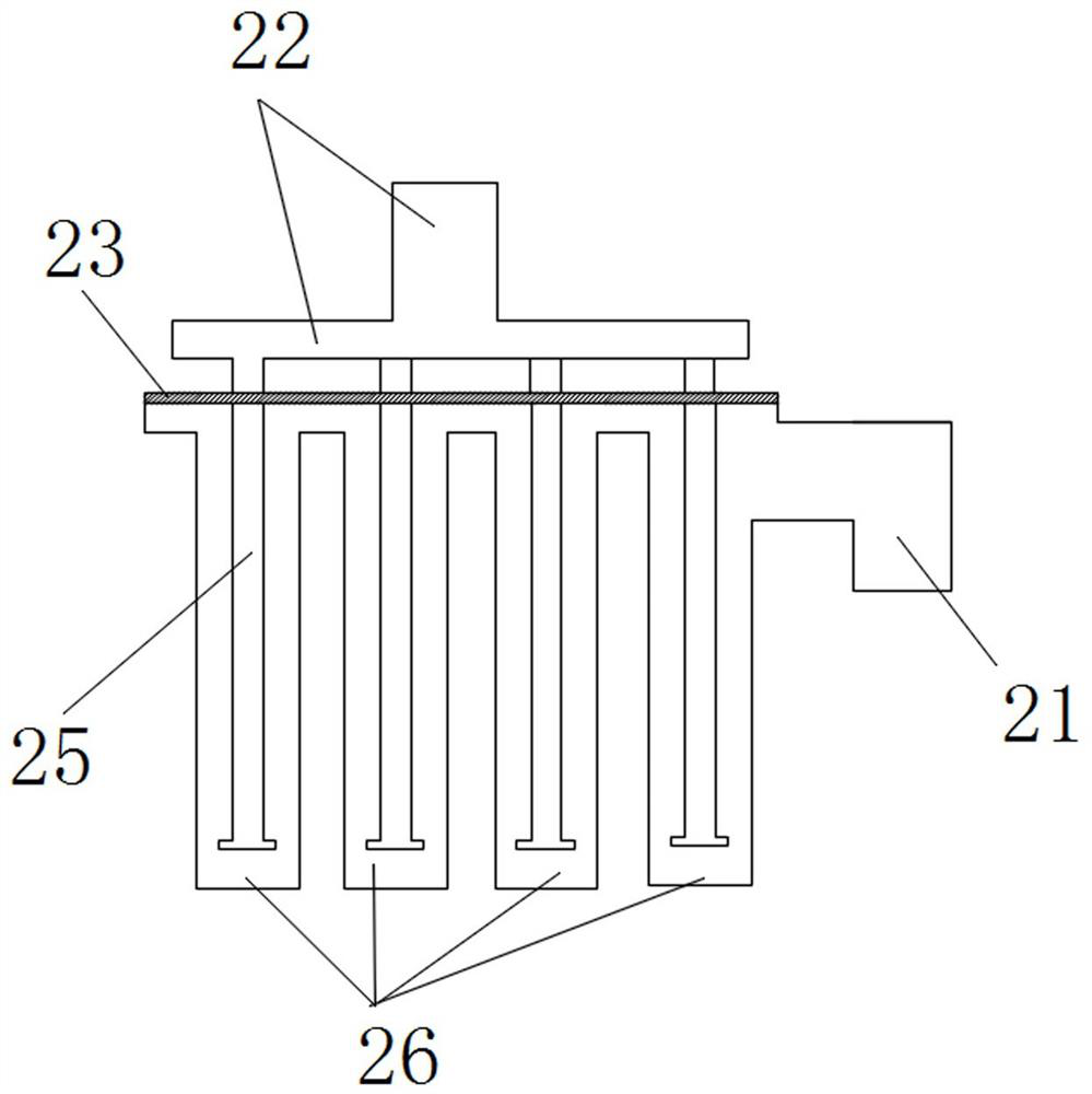
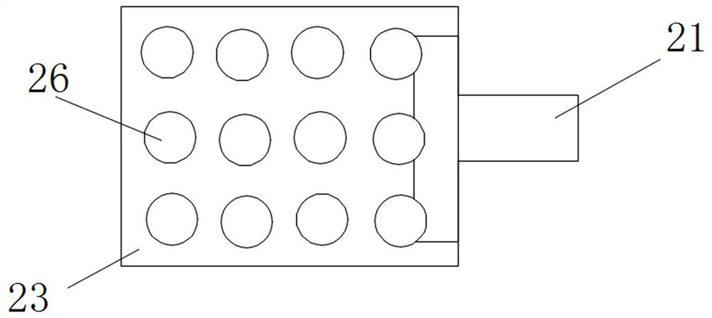
[0026] Such as Figure 1-5 As shown, an industrial waste gas heat recovery device of the present invention includes an evaporator 1 and a heat collection device 2 partially arranged in the cavity of the evaporator 1, and the heat collection device 2 includes a plurality of The heating tubes 26 distributed in a square matrix and the T-shaped smoke inlet 22 arranged above the evaporator 1, the plurality of heating tubes 26 are provided with a smoke branch pipe 25 in the inner cavity, and the plurality of smoke branch pipes 25 The smoke inlet ends are all welded on the horizontal section of the T-shaped smoke inlet 22, and a sealing plate 23 for preventing exhaust gas from overflowing is provided between the horizontal section of the T-shaped smoke inlet 22 and the upper ends of a plurality of heating pipes 26, and the said square One side of a plurality of heating pipes 26 distributed in a matrix is ​​provided with a smoke outlet 21, and the end of the vertical section of the T-...

Embodiment 2

[0029] Based on Embodiment 1, the primary dust removal device 41 includes multiple layers of detachable filter screens 41 .

[0030] It is convenient to replace the filter screen regularly, so as to keep the primary dust removal device 4 unimpeded.

[0031] The spraying device 32 includes a plurality of spraying heads arranged on the side wall of the dust removal chamber 31 .

[0032] The exhaust gas outlet 33 is disposed on the lower side of the shower device 32 .

[0033] The present invention is an industrial waste gas heat recovery device. By arranging a plurality of heating pipes 36 distributed in a square matrix in the evaporator 1, the cold water entering from the water injection port 11 on the evaporator 1 can be more fully combined with the plurality of heating pipes. The contact greatly increases the energy absorption efficiency of cold water, and secondly, by setting on the T-shaped smoke inlet 22 and the secondary dust removal device 3, the dust accumulation speed...


PUM


Abstract

The invention provides an industrial waste gas heat recovery device. The industrial waste gas heat recovery device comprises an evaporator and a heat collecting device. The heat collecting device comprises a plurality of heating pipes and a T-shaped smoke inlet, smoke outlet branch pipes are arranged in inner cavities of the multiple heating pipes, and the smoke inlet ends of the multiple smoke outlet branch pipes are welded to a horizontal section of the T-shaped smoke inlet. Smoke outlets are formed in one sides of the multiple heating pipes distributed in a square matrix, a primary dust removal device is arranged on the T-shaped smoke inlet, and a secondary dust removal device is arranged below the smoke outlets. The secondary dust removal device comprises a dust removal chamber, a spraying device, a waste gas exhaust port and a drain outlet formed in the bottom of the dust removal chamber. The multiple heating pipes distributed in the square matrix mode are arranged in the evaporator, the energy absorption area of cold water is greatly increased, then the dust accumulation speed in the heating pipes can be effectively reduced by arranging the primary dust removal device and thesecondary dust removal device, and therefore, the energy absorption efficiency is further improved.

Description

technical field [0001] The invention relates to the technical field of energy saving and environmental protection equipment, in particular to an industrial waste gas heat recovery device. Background technique [0002] Since the beginning of the 21st century, with the rapid growth of the global economy and the acceleration of global integration, the contradiction between energy supply and demand has become increasingly prominent, and an important aspect of economic competition among various countries is reflected in energy competition. superior. With the increasing tension of world energy and the rising energy prices, the global ecological environment is also deteriorating day by day. The shortage of energy and the high price cause the continuous increase of manufacturing cost and the continuous increase of market competition pressure. How to effectively save energy, reduce emissions and protect the environment has become a major international issue facing the international...

Claims


Application Information

Patent Timeline
IPC IPC(8): F28D7/10F28F19/01F22B1/18B01D50/00
CPCF28D7/103F28F19/01F22B1/18B01D50/60
Inventor 陈晨孙积文陈祥顺彭加华
Owner 四川陆亨能源科技有限公司
Learn More