Lubricating device for stamping equipment
A technology of lubricating device and stamping equipment, applied in the field of stamping equipment lubrication, can solve the problems of shortening the life of the die, reducing the precision, and the finish of the workpiece can not meet the requirements, and achieving the effect of saving stamping oil and preventing the shortening of the life.
- Summary
- Abstract
- Description
- Claims
- Application Information
AI Technical Summary
Problems solved by technology
Method used
Image
Examples
Embodiment 1
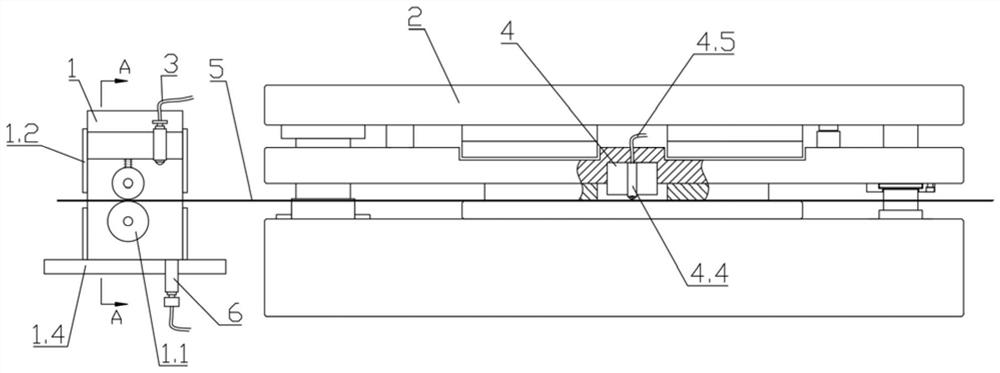
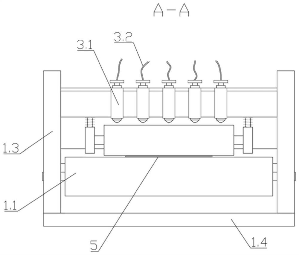
[0024] According to the manual attached figure 1 As shown, the present invention provides a lubricating device for stamping equipment, which includes a feeding mechanism 1, a mold 2, an oil tank, a first lubricating mechanism 3, a second lubricating mechanism 4, and a material belt 5, and the feeding mechanism 1 is located at the mold 2 On the feeding side, the material belt 5 passes through the feeding mechanism 1, enters from the feeding side of the mold 2 and passes through the mold 2, and passes through the discharging side of the mold 2 after stamping, the first lubricating mechanism 3 , the second lubricating mechanism 4 is arranged on the top of the material belt 5, the first lubricating mechanism 3 is arranged on the feeding mechanism 1, the second lubricating mechanism 4 is arranged on the mold 2, and the oil tank is connected with the first lubricating mechanism 3 and the second lubricating mechanism respectively. Mechanism 4 is connected.
[0025] The second lubric...
Embodiment 2
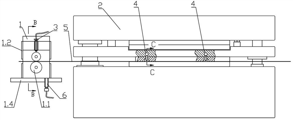
[0031] This embodiment is basically the same as Embodiment 1, the difference is that, according to the image 3 As shown, in this embodiment, the first lubricating mechanism 3 is arranged above the strip guide roller assembly 1.1, and the stamping oil is dropped on the guide roller assembly, and the stamping oil is indirectly applied by the rotation of the strip guide roller assembly 1.1. On the material belt 5, the first lubricating mechanism 3 includes a first oil pipe 3.4 and a first oil drip nozzle 3.3, the first oil drip nozzle 3.3 is connected with the oil tank through the oil pipe, and five first oil drip nozzles are arranged side by side along the width direction of the material belt 5 3.3 Connect with the oil pipe, and at the same time carry out drip lubrication treatment on the material belt 5.
[0032] As attached to the manual Figure 3-4 As shown, the second lubricating mechanism 4 is arranged on the mold 2, and the second lubricating mechanism 4 is evenly arrang...
PUM
 Abstract
Description
Claims
Application Information
 - R&D
- Intellectual Property
- Life Sciences
- Materials
- Tech Scout
- Unparalleled Data Quality
- Higher Quality Content
- 60% Fewer Hallucinations
Browse by: Latest US Patents, China's latest patents, Technical Efficacy Thesaurus, Application Domain, Technology Topic, Popular Technical Reports.
© 2025 PatSnap. All rights reserved.Legal|Privacy policy|Modern Slavery Act Transparency Statement|Sitemap|About US| Contact US: help@patsnap.com


