Fault judgment method, magnetic levitation compressor, air-conditioning unit and readable storage medium
A fault judgment and magnetic levitation technology, which is applied to compressors, machines/engines, refrigerators, etc., can solve problems such as controller control instability, avoid irreversible damage, avoid control instability, and improve processing speed.
- Summary
- Abstract
- Description
- Claims
- Application Information
AI Technical Summary
Problems solved by technology
Method used
Image
Examples
Embodiment 1
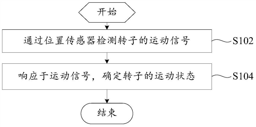
[0052] combine figure 1 and Figure 8 As shown, the embodiment of the first aspect of the present invention proposes a fault judgment method, the magnetic levitation compressor includes a rotor 100 and a position sensor 300, and the fault judgment method includes:
[0053] Step S102, detecting the movement signal of the rotor through the position sensor;
[0054] Step S104, in response to the motion signal, determine the motion state of the rotor.
[0055] The fault diagnosis method provided by the present invention is realized by receiving the motion signal sent by the position sensor 300. Specifically, the position sensor 300 can detect the detection part 200 on the rotor 100. When the position sensor 300 detects the detection part 200, that is When the detection part 200 on the rotor 100 rotates to one side of the position sensor 300, the position sensor 300 can output a kind of motion signal, when the position sensor 300 does not detect the detection part 200, the positi...
Embodiment 2
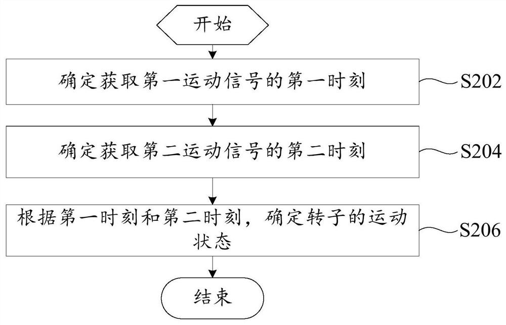
[0058] combine figure 2 and Figure 8 As shown, on the basis of the first embodiment, the position sensor 300 detects the detection part 200, the position sensor 300 outputs the first motion signal, the position sensor 300 does not detect the detection part 200, and the position sensor 300 outputs the second motion signal.
[0059] Fault judgment methods include:
[0060] Step S202, determining the first moment of acquiring the first motion signal;
[0061] Step S204, determining a second moment for acquiring a second motion signal;
[0062] Step S206, determine the motion state of the rotor according to the first moment and the second moment.
[0063] The step of determining the motion state of the rotor in response to the motion signal specifically includes: determining the first moment for obtaining the first motion signal; determining the second moment for obtaining the second motion signal; state of motion.
[0064] In this embodiment, the position sensor 300 can de...
Embodiment 3
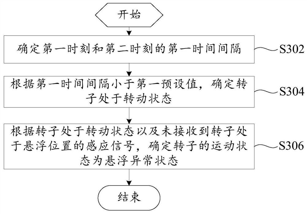
[0066] combine image 3 and Figure 8 As shown, in a specific embodiment of the above-mentioned embodiment, the fault judgment method includes:
[0067] Step S302, determining the first time interval between the first moment and the second moment;
[0068]Step S304, according to the fact that the first time interval is less than the first preset value, it is determined that the rotor is in a rotating state;
[0069] Step S306, according to the fact that the rotor is in a rotating state and no induction signal that the rotor is in a levitation position is received, it is determined that the motion state of the rotor is an abnormal levitation state.
[0070] According to the first moment and the second moment, the step of determining the motion state of the rotor specifically includes: determining the first time interval between the first moment and the second moment; determining that the rotor is rotating according to the first time interval being less than the first preset v...
PUM
 Abstract
Description
Claims
Application Information
 - Generate Ideas
- Intellectual Property
- Life Sciences
- Materials
- Tech Scout
- Unparalleled Data Quality
- Higher Quality Content
- 60% Fewer Hallucinations
Browse by: Latest US Patents, China's latest patents, Technical Efficacy Thesaurus, Application Domain, Technology Topic, Popular Technical Reports.
© 2025 PatSnap. All rights reserved.Legal|Privacy policy|Modern Slavery Act Transparency Statement|Sitemap|About US| Contact US: help@patsnap.com


