Method for heating furnace cylinder during damping down of blast furnace

A heating furnace and blast furnace technology, which is applied to blast furnaces, blast furnace details, blast furnace parts, etc., can solve the problems of inability to achieve flow, the temperature of newly generated slag and iron, and the porosity of blast furnace hearths. The effect of making up for heat loss and reducing recovery time

Inactive Publication Date: 2020-11-27
SHANXI TAIGANG STAINLESS STEEL CO LTD
View PDF6 Cites 0 Cited by
  • Summary
  • Abstract
  • Description
  • Claims
  • Application Information

AI Technical Summary

Problems solved by technology

In the actual production process, during the suffocation period of the blast furnace, there is no air flow into the hearth area, and the coke combustion basically stops, which cannot continuously provide heat to the hearth area.
At the same time, during the suffocation period of the blast furnace, due to the need to protect the cooling equipment and hearth refractories and prevent safety accidents, the cooling of the hearth area cannot be stopped synchronously. Although measures can be taken to reduce the cooling water in the hearth area, it is still It will cause part of the heat loss in the hearth area, resulting in a significant drop in the temperature of coke and retained slag iron in the hearth area
When the blast furnace is blown after the blast furnace is stuffy, the newly formed iron slag flows into the hearth, but because the temperature of the coke in the hearth area and the retained iron slag is too low, it will absorb a large amount of heat from the newly formed iron slag, resulting in the formation of iron slag. As the temperature drops, the fluidity of the newly formed slag iron becomes poor and cannot flow
Moreover, in the process of temperature drop, new slag shells will be formed, so that the newly generated slag and iron cannot be completely discharged, and gradually accumulate in the hearth, resulting in a smaller porosity of the blast furnace hearth, and the blast furnace does not accept the air volume, thus making the blast furnace The air supply recovery time becomes longer, and the coke ratio and fuel specific consumption increase during the recovery period

Method used


Image

  • Method for heating furnace cylinder during damping down of blast furnace
  • Method for heating furnace cylinder during damping down of blast furnace

Examples


Embodiment

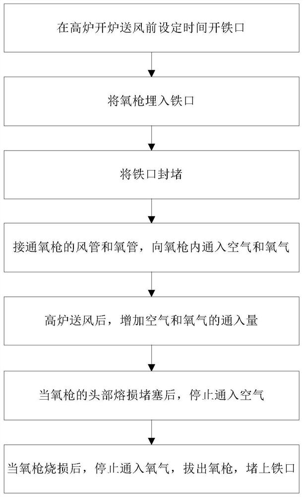
[0069] In this embodiment, the hearth is heated in the later stage of the blast furnace suffocation through the following steps: 24 hours before the blast furnace is opened and air is sent, the iron hole is drilled with a 100mm diameter variable diameter drill, drilled until the coke is seen, and then burned with oxygen Burn out the space from the iron hole to the front end of the iron hole to obtain a 100mm diameter iron hole; from the position of the oxygen lance at 2500mm from the end of the oxygen lance head to the position 500mm from the end of the oxygen lance head, use 14# lead wire in the oxygen Wrap 5 turns on the gun, and the interval between two adjacent turns of lead wire is 500mm; from the position of the oxygen lance at 2500mm from the end of the oxygen lance head to the position of 500mm from the end of the oxygen lance head, use 5mm asbestos The rope is wound on the oxygen lance for 5 sections, and the head spacing of each two adjacent asbestos rope winding secti...


PUM

PropertyMeasurementUnit
lengthaaaaaaaaaa

Abstract

The invention discloses a method for heating a furnace cylinder during damping down of a blast furnace. The method comprises the following steps: (1) setting a time to open an iron notch before blastfurnace blowing in; (2) embedding an oxygen lance into the iron notch; (3) plugging the iron notch; (4) connecting an air pipe and an oxygen pipe of the oxygen lance, and introducing air and oxygen into the oxygen lance; (5) increasing the inflow of air and oxygen after blast of the blast furnace; (6) when the head of the oxygen lance is damaged and blocked, stopping introducing air; and (7) afterthe oxygen lance is burnt, stopping introducing oxygen, pulling out the oxygen lance, and plugging the iron notch. According to the method, the furnace cylinder can be heated in the later period of damping down of the blast furnace, the heat loss of the furnace cylinder area in the damping down period of the blast furnace can be compensated, the sufficient heat storage of the furnace cylinder inthe damping down period of the blast furnace is ensured, and the blast furnace blowing recovery time, and the coke ratio and the fuel ratio in the recovery period are reduced.

Description

Technical field [0001] The invention relates to the technical field of iron and steel smelting, and in particular to a method for heating a hearth during a blast furnace stuffing. Background technique [0002] Blast furnace suffocated furnace means that the blast furnace is out of production for a long time without replacement or repair. It is a state of the blast furnace supporting hot blast stove. In the actual production process, there is no air flow into the hearth area during the stuffing of the blast furnace, and the combustion of coke basically stops, which cannot continue to provide heat to the hearth area. At the same time, during the stuffing of the blast furnace, due to the need to protect the cooling equipment and refractory materials of the hearth, and to prevent safety accidents, the cooling of the hearth area cannot be stopped synchronously. Although measures can be taken to reduce the amount of cooling water in the hearth area, but still It will cause part of the...

Claims


Application Information

Patent Timeline
Patent Type & Authority Applications(China)
IPC IPC(8): C21B7/00
CPCC21B7/00
Inventor 祁虎拴巩黎伟赵新民陈树文郑伟宋建忠刘太林陈国安胡志鸿王新华
Owner SHANXI TAIGANG STAINLESS STEEL CO LTD
Why Eureka
Try Eureka