Rotary ultrasonic-microwave combined microfluid extraction equipment

An ultrasonic and rotary technology, applied in the field of microfluidic extraction equipment, can solve the problems of complex structure, high production process requirements, long extraction time, etc., and achieve the effect of increasing high specific surface area, improving extraction efficiency, and accelerating extraction speed

Pending Publication Date: 2020-11-27
KUNMING UNIV OF SCI & TECH
View PDF14 Cites 1 Cited by
  • Summary
  • Abstract
  • Description
  • Claims
  • Application Information

AI Technical Summary

Problems solved by technology

[0004] The invention patent of Chinese Patent Publication No. CN110339593A discloses a high-throughput liquid-liquid extraction microfluidic device and its extraction method. The device and method increase the fluid contact area by designing multiple microfluidic channels and extraction units, and can Continuously feed and stably transport the sample solution and extractant, but the parallel connection of microfluidic channels has high requirements on the manufacturing process, the fluid flow distribution is relatively complicated, and the flow rate is too slow, so the fluid extraction efficiency is not high
Chinese Patent Publication No. CN108654138A discloses a centrifugal force microfluidic extraction device and its extraction method. Under the action of centrifugal force, the aqueous phase and the organic phase spread into a two-phase liquid film, forming a static interface and enlarging the mass transfer area. However, the present invention extracts Long time and complex structure, not suitable for continuous large-scale production

Method used


Image

  • Rotary ultrasonic-microwave combined microfluid extraction equipment
  • Rotary ultrasonic-microwave combined microfluid extraction equipment
  • Rotary ultrasonic-microwave combined microfluid extraction equipment

Examples


Embodiment 1

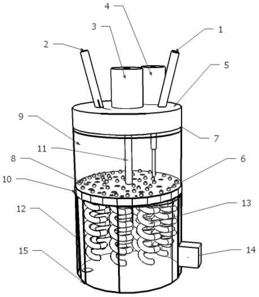
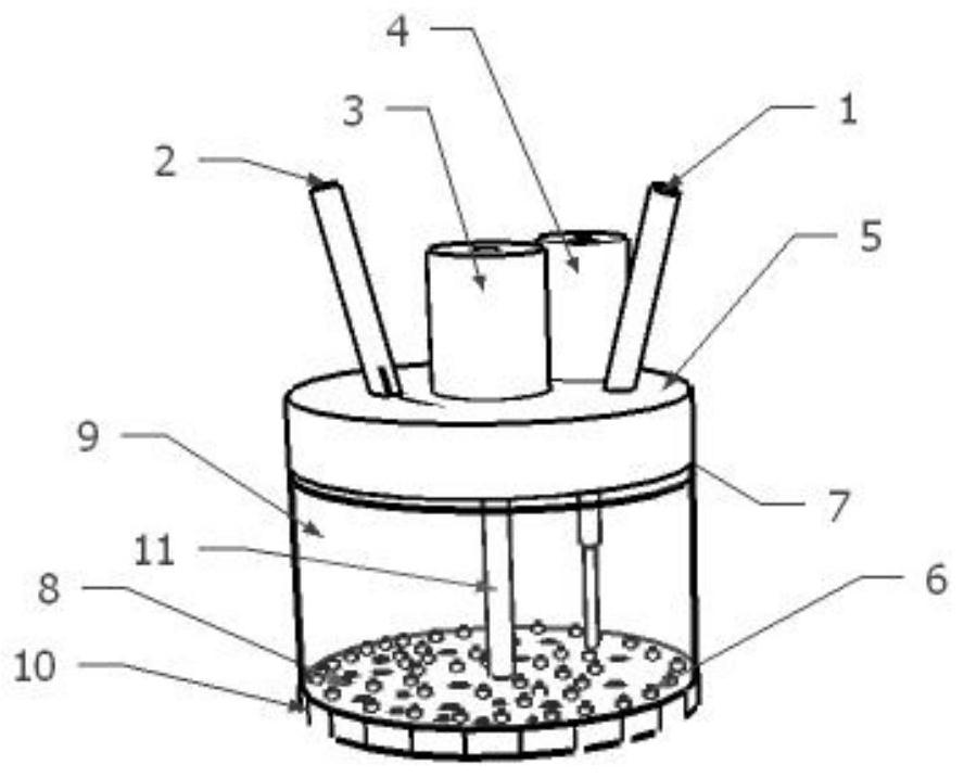
[0028] like figure 1 As shown, the rotary ultrasonic-microwave combined microfluidic extraction device includes a liquid collecting chamber cover 5 , an ultrasonic mixing liquid collecting chamber 9 and a microwave extraction chamber 12 .

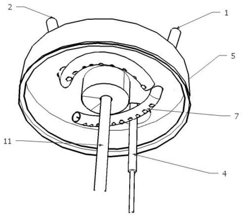
[0029] The lid 5 of the liquid collection chamber is equipped with a water-phase feeding micro-tube 1 and an oil-phase feeding micro-tube 2, and the ends of the water-phase feeding micro-tube 1 and the oil-phase feeding micro-tube 2 are arc-shaped curved horizontal sections, and the curved sections are They are respectively fixed on the bottom end of the lid 5 of the liquid collection chamber, the inner diameter of each microtube is 3 mm, and each microtube is provided with 15 liquid column cutting holes 7, and the diameter of the micropores is 0.7 mm, which can separate the water phase and the oil phase. The liquid column is cut into small diameter liquid columns or droplets. A motor 3 and an ultrasonic exciter 4 are fixed on the cover 5 ...


PUM

PropertyMeasurementUnit
Pore diameteraaaaaaaaaa
The inside diameter ofaaaaaaaaaa
Average heightaaaaaaaaaa

Abstract

The invention discloses rotary ultrasonic-microwave combined microfluid extraction equipment. The equipment comprises a water-phase feeding micropipe, an oil-phase feeding micropipe, an engine, a contact mixing rotary table and an ultrasonic exciter, an ultrasonic mixing liquid collecting chamber, a microwave extraction chamber, a microwave generator and a microwave extraction micro-channel; tailends of the water-phase feeding micropipe and the oil-phase feeding micropipe are arc-shaped bent horizontal sections and are respectively fixed at the bottom end of the liquid collecting chamber cover; liquid column cutting holes are formed in the micropipe; the engine is connected with the contact mixing rotary table through a rotary shaft; micropores are formed in the contact mixing rotary table and connected with the microwave extraction micro-channel through an extraction chamber inlet hole; and the microwave generator is arranged on the outer wall of the microwave extraction chamber. According to the invention, a sample solution and an extraction agent can be continuously and stably conveyed into the equipment, the combination speed of the sample solution and the extraction agent isaccelerated, and the fluid contact area and extraction rate are improved.

Description

technical field [0001] The invention relates to a rotary ultrasonic-microwave combined micro-fluid extraction device, which belongs to the field of micro-fluid extraction devices. [0002] technical background [0003] Extraction is the use of the difference in solubility or distribution coefficient of a substance in two immiscible (or slightly soluble) solvents to transfer a substance from one solvent to another. As an important separation unit operation, extraction technology is widely used in chemistry, chemical industry, metallurgy, food processing and other fields. Compared with traditional extraction technology, microfluidic extraction technology extracts fluid by using micro-sized microchannels, which has the advantages of less amount of extractant, high extraction efficiency, less emulsification during extraction, and high safety. It has begun to be valued and applied in the field of chemical metallurgy, but most of the existing microfluidic extraction equipment has ...

Claims


Application Information

Patent Timeline
IPC IPC(8): B01D11/04B01J19/10B01J19/12
CPCB01D11/0496B01D11/0423B01D11/0419
Inventor 孙晓飞周云
Owner KUNMING UNIV OF SCI & TECH
Why Eureka
Try Eureka