Wire cutting cold saw alloy tool bit tooth shifting mechanism

A wire cutting and alloy knife technology, applied in the field of wire cutting and cold saw alloy blade gear shifting mechanism, can solve the problems of large cutting volume, large water volume, fast wear of grinding wheel, etc., achieve high repeat positioning accuracy, simple structure, and convenient application Effect

Pending Publication Date: 2020-11-24
临沂和通精密机械设备有限公司
View PDF0 Cites 0 Cited by
  • Summary
  • Abstract
  • Description
  • Claims
  • Application Information

AI Technical Summary

Problems solved by technology

[0003] The processing of the existing cold saw alloy cutter head is done on a special grinding machine, and the teeth are shifted with a two-axis cross slide table. When grinding the front angle of the cutter head, the amount of cutting is large and the wear of the grinding wheel is fast. The shape of the grinding wheel needs to be disassembled every day. It is very labor-intensive, and wire cutting replaces grinding to cut the rake angle shape and finish of the cutter head, which meet the technical requirements. However, wire cutting requires a large amount of water and many impurities, and generally the space is small, while the ball wire of the two-axis servo slide table The rod and servo motor are bulky and afraid of water ingress

Method used


Image

  • Wire cutting cold saw alloy tool bit tooth shifting mechanism
  • Wire cutting cold saw alloy tool bit tooth shifting mechanism
  • Wire cutting cold saw alloy tool bit tooth shifting mechanism

Examples


Embodiment Construction

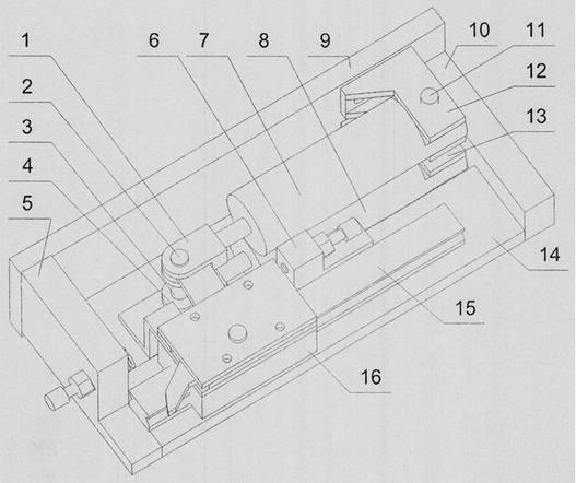
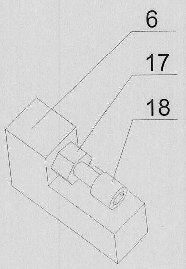
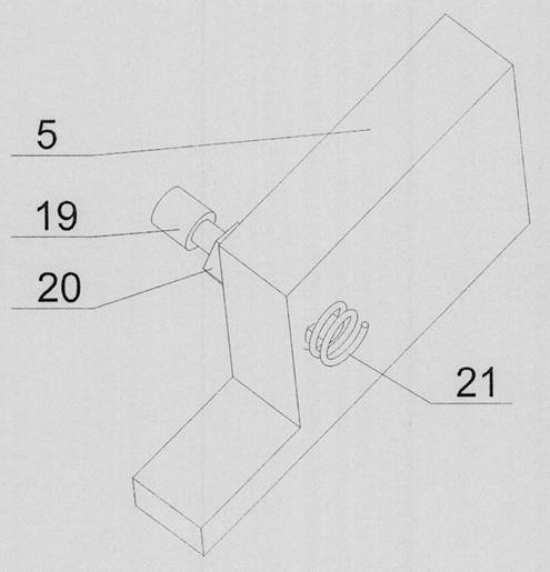
[0013] As shown in the figure, the present invention is provided with a power cylinder frame 12 and a damping cylinder frame 13 on the front mounting plate 9, a left baffle plate 5 and a right baffle plate 10 are arranged at both ends of the front mounting plate 9, and on the power cylinder frame 12 There is a power cylinder 7 connected with the cylinder pendulum shaft 11, the power cylinder 7 is provided with a power cylinder Y joint 1, and the rotating shaft 2 above the power cylinder Y joint 1 is connected with the gear head 25, and the damping cylinder frame 13 is provided with a cylinder The damping cylinder 8 connected to the pendulum shaft 11 is provided with a damping cylinder Y joint 4, the damping cylinder Y joint 4 is connected to the damping cylinder connecting frame 26 with the rotating shaft 3 below the damping cylinder 8, and a bottom plate is provided between the left baffle plate 5 and the right baffle plate 10 14. The bottom plate 14 is provided with a guide r...


PUM


Abstract

The invention relates to a wire cutting machine tool, in particular to a wire cutting cold saw alloy tool bit tooth shifting mechanism. The mechanism is characterized in that a power cylinder frame and a damping cylinder frame are arranged on a front mounting plate; a left baffle plate and a right baffle plate are arranged at two ends of the front mounting plate; a power cylinder connected with acylinder swing shaft is arranged on the power cylinder frame; a power cylinder Y joint is arranged on the power cylinder; a rotating shaft above the power cylinder Y joint is connected with a tooth shifting head; a damping cylinder connected with the cylinder swing shaft is arranged on the damping cylinder frame; a damping cylinder Y joint is arranged on the damping cylinder; a rotating shaft below the damping cylinder Y joint is connected with a damping cylinder connecting frame; a bottom plate is arranged between the left baffle plate and the right baffle plate; a guide rail and a stop blockare arranged on the bottom plate; and a sliding block is arranged on the guide rail. Through the above arrangement, when a cold saw alloy is processed by wire cutting, the requirements that the wirecutting cold saw alloy tool bit tooth shifting mechanism is simple in structure, convenient to apply, high in repeated positioning accuracy and free of water are met.

Description

technical field [0001] The invention relates to a wire cutting machine tool, in particular to a gear shifting mechanism for a wire cutting cold saw alloy cutter head. [0002] technical background [0003] The processing of the existing cold saw alloy cutter head is done on a special grinding machine, using a two-axis cross slide table to shift the teeth. When grinding the front angle of the cutter head, the cutting volume is large and the grinding wheel wears quickly, so the shape of the grinding wheel needs to be disassembled every day. It is very labor-intensive, and wire cutting replaces grinding to cut the rake angle shape and finish of the cutter head, which meet the technical requirements. However, wire cutting requires a large amount of water and many impurities, and the general space is also small. The rod and servo motor are bulky and afraid of water ingress. Contents of the invention [0004] The object of the present invention is to provide a wire cutting cold ...

Claims


Application Information

Patent Timeline
Patent Type & Authority Applications(China)
IPC IPC(8): B23H7/02B23H11/00
CPCB23H7/02B23H11/00
Inventor 路子珍魏运凯李磊
Owner 临沂和通精密机械设备有限公司
Why Eureka
Try Eureka