Iron alloy particles and method for producing iron alloy particles

A manufacturing method and ferroalloy technology, applied in transportation and packaging, metal processing equipment, magnetic materials, etc., can solve the problem of increased loss of magnetic components and achieve good high-frequency characteristics and high saturation magnetic flux density

Active Publication Date: 2020-11-20
MURATA MFG CO LTD
View PDF6 Cites 0 Cited by
  • Summary
  • Abstract
  • Description
  • Claims
  • Application Information

AI Technical Summary

Problems solved by technology

Therefore, magnetic components using these materials have a problem of increased loss

Method used


Image

  • Iron alloy particles and method for producing iron alloy particles
  • Iron alloy particles and method for producing iron alloy particles
  • Iron alloy particles and method for producing iron alloy particles

Examples


Embodiment 1-1

[0067] An alloy ribbon having a composition of FeSiPBCCu produced by a single-roll quenching method was prepared as a raw material. The composition used in the embodiment is Fe 84.8 Si 0.5 B 9.4 P 3.5 Cu 0.8 C 1 . This alloy ribbon was pulverized using a high-speed rotary pulverizer.

[0068] As a high-speed rotary pulverizer, a HYBRIDIZATION SYSTEM (manufactured by Nara Machinery Manufacturing Co., Ltd., NHS-0 type) was used. Table 1 shows the processing time (rotation time of the rotor) and peripheral speed (rotation speed of the rotor).

[0069] After pulverization, heat treatment was performed at 500° C. for 1 hour. Through the above operations, alloy particles are produced.

Embodiment 1-2~ Embodiment 1-8

[0071] Alloy particles were produced by performing the same treatment as in Example 1-1 except that the treatment time and peripheral speed were changed to the values ​​shown in Table 1.

Embodiment 2-1

[0098] An alloy ribbon having a composition of FeSiPBCCu produced by the single-roll quenching method was prepared as a raw material in the same manner as in Example 1-1. After the alloy ribbon was heat-treated under the conditions shown in Table 2, alloy particles were produced by performing the same treatment as in Example 1-1.


PUM

PropertyMeasurementUnit
thicknessaaaaaaaaaa
diameteraaaaaaaaaa
thicknessaaaaaaaaaa

Abstract

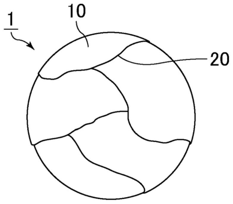
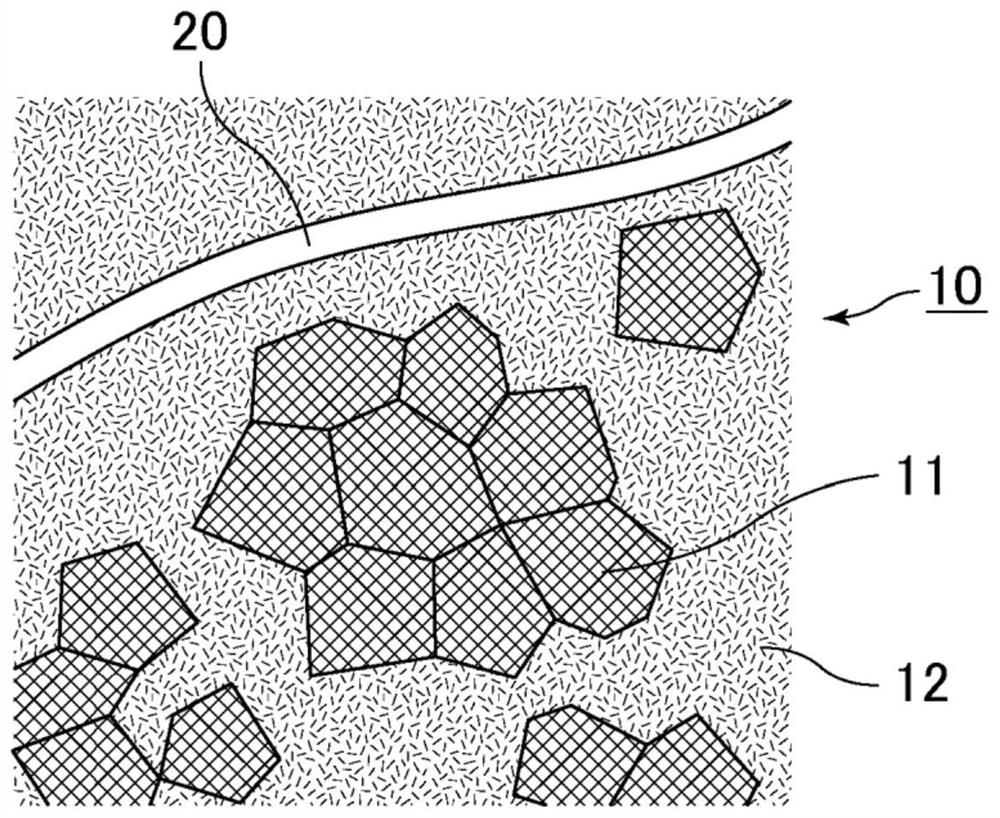
Iron alloy particles according to the present invention comprise an iron alloy and are configured from a plurality of mixed-phase particles including an amorphous material and nanocrystals having a crystallite diameter of 10-100 nm. The iron alloy particles comprise a grain boundary layer between the mixed-phase particles, and the iron alloy comprises Fe, Si, P, B, C, and Cu in the composition thereof.

Description

technical field [0001] The present invention relates to iron alloy particles and a method for producing iron alloy particles. Background technique [0002] Conventionally, iron, silicon steel, and the like have been used as soft magnetic materials used in various reactors, motors, transformers, and the like. Although these have a high magnetic flux density, crystal magnetic anisotropy is large, and therefore, hysteresis is large. Therefore, magnetic components using these materials have a problem of increased loss. [0003] Aiming at such problems, a kind of soft magnetic alloy powder is disclosed in Patent Document 1, which consists of composition formula: Fe 100-x- y Cu x B y (wherein, in atomic %, 1<x<2, 10≤y≤20) means that crystal grains having a body-centered cubic structure with an average particle diameter of 60 nm or less are dispersed in the amorphous matrix with a volume fraction of 30% or more organization. [0004] prior art literature [0005] pate...

Claims


Application Information

Patent Timeline
Patent Type & Authority Applications(China)
IPC IPC(8): B22F1/00B22F9/04C22C38/00C22C45/02H01F1/153B22F1/054B22F1/08
CPCC22C38/00C22C45/02C22C38/16C22C38/002C22C38/02C22C2200/02C22C2200/04C22C33/0257B22F2009/048B22F2009/045B22F2999/00B22F2998/10C22C2202/02H01F1/15341H01F1/15308B22F1/054B22F1/07B22F1/08B22F1/142B22F9/04B22F2301/35
Inventor 中野学
Owner MURATA MFG CO LTD
Why Eureka
Try Eureka