Quick response type recoverable fuse

A fast response, fuse technology, applied in electrical components and other directions, can solve the problems of large heat generation and long response time, and achieve the effect of shortening consumption time, reducing heat, and speeding up charging speed.

Pending Publication Date: 2020-11-20
刘剑
View PDF7 Cites 0 Cited by
  • Summary
  • Abstract
  • Description
  • Claims
  • Application Information

AI Technical Summary

Problems solved by technology

[0004] The purpose of the present invention is to solve the shortcomings of the prior art that the recoverable fuse has

Method used


Image

  • Quick response type recoverable fuse
  • Quick response type recoverable fuse
  • Quick response type recoverable fuse

Examples


Embodiment 1

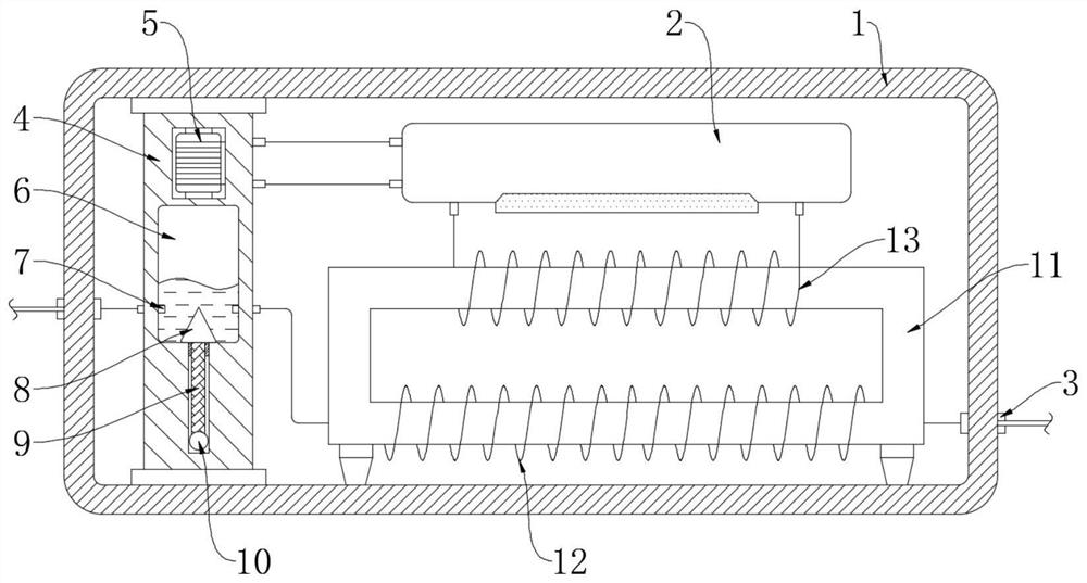
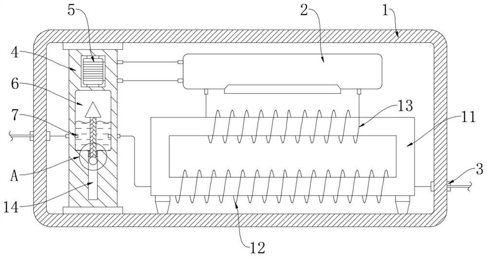
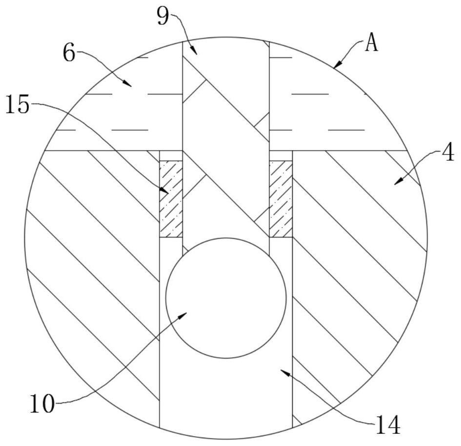
[0022] refer to Figure 1-3 , a fast-response resettable fuse, comprising an insulating case 1 and two terminals 3 fixedly installed on the insulating case 1, a circuit breaker 2, an insulating column 4 and an iron core 11 are fixedly arranged in the insulating case 1, A first coil 12 and a second coil 13 are wound in parallel on the iron core 11, and the second coil 13 is electrically connected to the converter 2, the first coil 12 and the second coil 13 are coupled to each other, and the two together form a set of mutual inductance Coil, the insulating column 4 is provided with a sealing groove 6 and a chute 14 that communicate with each other, and a sealing ring 15 is clamped at the connection between the chute 14 and the sealing groove 6, and the sealing ring 15 can prevent the conductive liquid from entering the chute 14, and the sliding A floating plate 9 is slidably arranged in the groove 14, and the upper end and the lower end of the floating plate 9 are respectively f...

Embodiment 2

[0034] refer to Figure 4 , the present embodiment differs from Embodiment 1 in that: a plurality of permanent magnets 16 are arranged horizontally in the circumferential direction of the insulating column 4, and each permanent magnet 16 is located below the sealing groove 6, and the polarity of the plurality of permanent magnets 16 The orientations are set to be the same, and a permanent magnet plate 17 is hermetically installed inside the floating block 8 , and the polarity orientation of the permanent magnet plate 17 is the same as that of the permanent magnet plate 16 .

[0035] In the use of this embodiment, the magnetic field force between the permanent magnet plate 17 and the permanent magnet 16 is greater than the magnetic field force between the counterweight 10 and the permanent magnet 16, and non-ferromagnetic materials can also be used to make the counterweight 10;

[0036] After the solenoid coil 5 is fed with electric current, the solenoid coil 5 can generate a m...


PUM


Abstract

The invention discloses a quick response type recoverable fuse. The quick response type recoverable fuse comprises an insulating shell and two wiring terminals fixedly installed on the insulating shell; a circuit changer, an insulating column and an iron core are fixedly arranged in the insulating shell; a first coil and a second coil are wound on the iron core in parallel; the second coil is electrically connected with the circuit changer; a sealing groove and a sliding groove which are communicated with each other are formed in the insulating column; a sealing ring is clamped at the joint ofthe sliding groove and the sealing groove; a floating plate is arranged in the sliding groove in a sliding mode; the upper end and the lower end of the floating plate are fixedly connected with a floating block and a balancing weight respectively; the floating block is located in the sealing groove; and a solenoid coil electrically connected with the circuit changer is fixedly installed on the upper portion of the insulating column. The fuse is high in response speed. Compared with a common fuse using a bimetallic strip as an on-off part, the temperature in the fuse will not be greatly increased, and fatigue damage is not likely to be generated.

Description

technical field [0001] The invention relates to the technical field of circuit protection equipment, in particular to a fast-response resettable fuse. Background technique [0002] As a circuit protection device, fuses are widely used in power distribution systems, control systems, and defense systems. They are mainly divided into two types. The other is a one-time fuse, which uses the heat generated by the resistance to melt the melt, thereby disconnecting the circuit. [0003] When the existing recoverable fuse is used repeatedly, the metal sheet will be deformed multiple times to cause wear, and when the current increases, the heat generated at the connection between the metal sheet and the contact post will also increase significantly, resulting in a rapid rise in the internal temperature of the fuse , accelerates the aging of the fuse. In addition, it takes a certain amount of time for the metal sheet to heat up to the deformation temperature, resulting in a longer res...

Claims


Application Information

Patent Timeline
IPC IPC(8): H01H87/00
CPCH01H87/00
Inventor 刘剑
Owner 刘剑
Why Eureka
Try Eureka