
A shielded fixed probe device and test method based on electric energy meter ripple test

An electric energy meter, ripple technology, applied in shielding device, measuring device, measuring device casing, etc., can solve the problem of external interference of waveform, and achieve the effect of avoiding loop interference, stable connection, and stable contact.

Active Publication Date: 2021-07-30
ANHUI ZENITH ELECTRICITY & ELECTRONICS
View PDF6 Cites 0 Cited by
  • Summary
  • Abstract
  • Description
  • Claims
  • Application Information

AI Technical Summary

Problems solved by technology

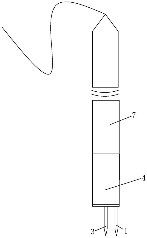
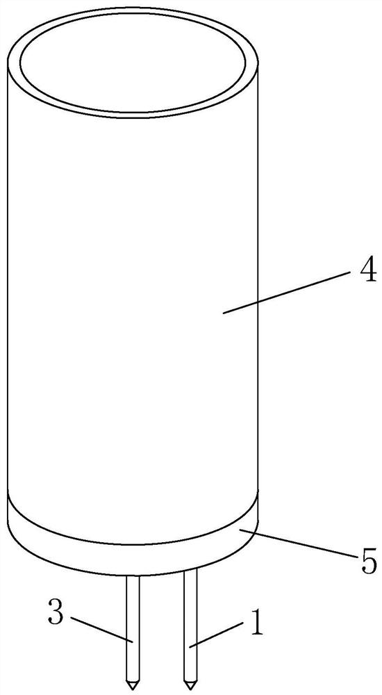
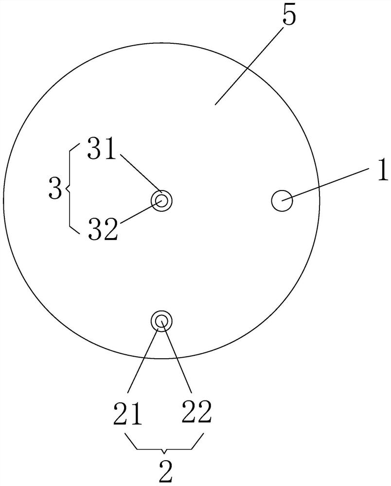
[0004] In order to solve the technical problem that the waveform measured by the existing ripple test equipment has external interference, which will cause the cover to be opened and recorded, the present invention provides a shielded and fixed probe device and a test method based on the ripple test of the electric energy meter

Method used


Image

  • A shielded fixed probe device and test method based on electric energy meter ripple test
  • A shielded fixed probe device and test method based on electric energy meter ripple test
  • A shielded fixed probe device and test method based on electric energy meter ripple test

Examples


Embodiment 1

[0058] see Figure 1-5 , this embodiment provides a shielded fixed probe device based on the electric energy meter ripple test, the device is used to connect a probe 7 and a carrier terminal base 6 of the electric meter. The shielded and fixed probe device is a carrier connected between the probe 7 and the carrier terminal base 6 of the ammeter, and can be used as a separate product, or combined with the probe 7 to form a new product, and can also be used as a part of the ripple test equipment. Wherein, the shielded fixed probe device includes a metal shielding column 4, a metal shielding chassis 5, a negative pin 1, a positive pin 1 3, a positive pin 2 2, a voltage detection module 1, a voltage detection module 2, an electronic switch and a controller .

[0059] The metal shielding column 4 is a hollow structure, and an insertion hole is opened at one end. The probe 7 is plugged into the socket hole, the negative electrode of the probe 7 is in contact with the metal shieldi...

Embodiment 2

[0075] see Image 6 , this embodiment provides a shielded fixed probe device based on the electric energy meter ripple test, which adds a metal grounding pin 8 on the basis of Embodiment 1. One end of the metal ground pin 8 is fixed on the end surface of the metal shielding chassis 5 , and the other end can be in contact with the ground terminal of the carrier terminal base 6 of the ammeter. The metal grounding pin 8 can realize the grounding function, and can also play the role of limiting and positioning at the same time, so that the device and the carrier terminal base 6 of the electric meter are fixed more firmly, and the probe 7 is convenient for testing.

Embodiment 3

[0077] This embodiment provides a shielded and fixed probe device based on the electric energy meter ripple test, which adds a power resistor on the basis of Embodiment 1. There is at least one power resistor, and the two ends of the power resistor are electrically connected to the negative pin 1 and the positive pin one 3 / the positive pin two 2 . The power resistor can exist as a load resistor required for testing to realize on-load measurement, and the test is more convenient and efficient.


PUM

PropertyMeasurementUnit
diameteraaaaaaaaaa

Abstract

The invention discloses a shielding fixed probe device and a testing method based on electric energy meter ripple testing. The device includes a metal shielding column, a metal shielding chassis, a negative pole pin, a positive pole pin one, a positive pole pin two, a voltage detection module one, a voltage detection module two, an electronic switch and a controller. The metal shielding chassis is fixed on the other end of the metal shielding column, the positive pole pin 1 includes metal pin 1 and insulating wrapping layer 1, and the positive pole pin 2 includes metal pin 2 and insulating wrapping layer 2. The positive pole of the probe is in contact with metal pin one and metal pin two, and is electrically connected to the positive pole of the carrier DC output of the ammeter carrier terminal base. The negative pole of the probe passes through the metal shielding column, the metal shielding chassis, and the negative pin and the ammeter carrier terminal base in turn. The negative pole of the carrier DC output is electrically connected. The invention makes the connection more stable, does not need to be supported by both hands after being placed correctly, is easy to operate, can reduce external interference, does not generate a record of opening the cover, and can be conveniently tested.

Description

technical field [0001] The invention relates to a shielded and fixed probe device in the technical field of ripple testing, in particular to a shielded and fixed probe device based on electric energy meter ripple testing, and also relates to a method for testing electric energy meter ripple including the device. Background technique [0002] Ripple is a phenomenon caused by the voltage fluctuation of the DC stabilized power supply, because the DC stabilized power supply is generally formed by the rectification and voltage stabilization of the AC power supply, which inevitably has some The AC component, this AC component superimposed on the DC stability is called ripple. The ripple size of the carrier output terminal of the ammeter is related to the stability of the power system. In the actual measurement process, the profile waveform is often composed of ripple and noise, that is, there are many interference signals. The main reasons are: 1. The bandwidth of the oscilloscop...

Claims


Application Information

Patent Timeline
Patent Type & Authority Patents(China)
IPC IPC(8): G01R29/26G01R1/18G01R11/04G01R1/04G01R1/20
CPCG01R1/0416G01R1/18G01R1/203G01R11/04G01R29/26
Inventor 刘洁左勇马波
Owner ANHUI ZENITH ELECTRICITY & ELECTRONICS
Learn More