
Single-end-face heat pipe anti-scaling evaporator

An evaporator and anti-scaling technology, which is applied in chemical instruments and methods, heating water/sewage treatment, special treatment targets, etc., can solve the problems of limited heater working range, increased equipment manufacturing cost, high and complex equipment, etc. Achieve the effects of reduced steel volume and space volume, simple and convenient maintenance, and increased concentration ratio

Pending Publication Date: 2020-11-20
北京璟航环境技术有限公司
View PDF0 Cites 2 Cited by
  • Summary
  • Abstract
  • Description
  • Claims
  • Application Information

AI Technical Summary

Problems solved by technology

The disadvantage is that the working range of the heater is limited in principle, and it can only operate within a certain concentration range. If it exceeds a certain concentration, scaling on the heating surface of the tube side is inevitable.
[0009] Second, whether it is a forced circulation heater or a heater operated by other methods such as falling film or rising film, there will be a problem of fouling inside the tube if the material concentration exceeds a certain level
[0010] Third, the evaporator in the form of a forced circulation heater still has a problem of requiring an evaporation chamber. After heating, the superheated material needs to enter a relatively low-pressure evaporation chamber for flash evaporation to complete a concentration step. After several consecutive such steps, To achieve the purpose of concentration
The existence of the evaporation chamber makes the whole device very large and complicated, and at the same time increases the manufacturing cost of the device

Method used


Image

  • Single-end-face heat pipe anti-scaling evaporator
  • Single-end-face heat pipe anti-scaling evaporator

Examples


Embodiment Construction

[0041] The following will clearly and completely describe the technical solutions in the embodiments of the present invention with reference to the accompanying drawings in the embodiments of the present invention. Obviously, the described embodiments are only some, not all, embodiments of the present invention. Based on the embodiments of the present invention, all other embodiments obtained by persons of ordinary skill in the art without creative efforts fall within the protection scope of the present invention.

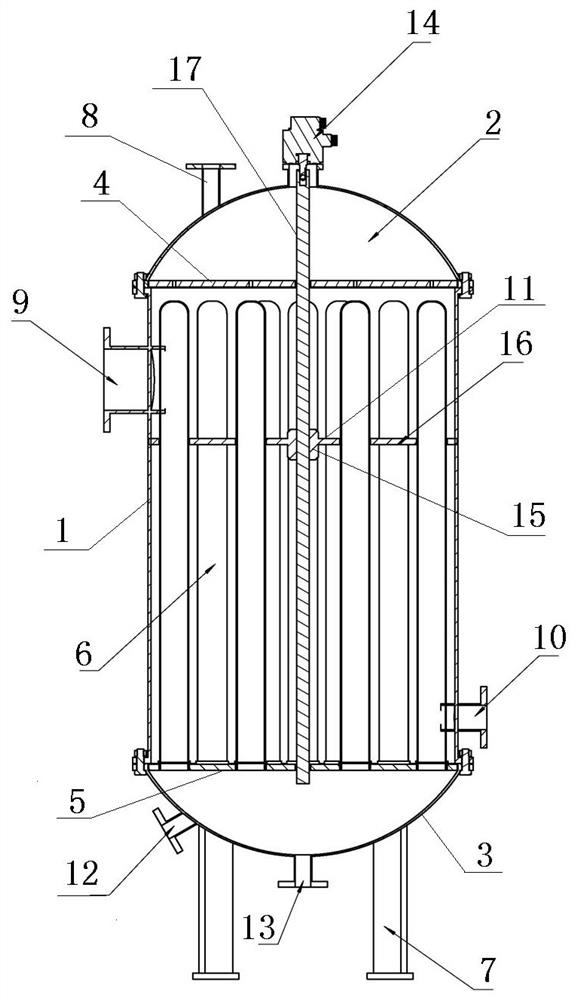
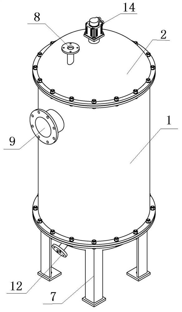
[0042] Such as Figure 1 to Figure 2 As shown, the single-end heat pipe anti-fouling evaporator includes a shell, a heat pipe 6, a first end face 4, a second end face 5, a descaling unit and a bracket 7;

[0043] The single-end heat pipe anti-fouling evaporator is placed vertically;

[0044] The housing includes a cylindrical shell body 1, a first cover body 2 and a second cover body 3; the first cover body 2 is fixedly installed on the upper end surface of the cy...


PUM

PropertyMeasurementUnit
diameteraaaaaaaaaa
lengthaaaaaaaaaa

Abstract

The invention discloses a single-end-face heat pipe anti-scaling evaporator. The evaporator comprises a shell, a heat conduction pipe, a first end face, a second end face, a descaling unit and a support. The shell comprises a cylindrical shell body, a first cover body and a second cover body, the first cover body and the second cover body are fixedly installed on the upper end face and the lower end face of the cylindrical shell body through flanges respectively, the first end face is located between the first cover body and the upper end face of the cylindrical shell body, and the second endface is located between the second cover body and the lower end face of the cylindrical shell body. One end of the heat conduction pipe is closed and the other end is open. The open end of the heat conduction pipe is welded to the hole of the second end face. The evaporator has the beneficial effects that scaling accumulation is effectively avoided, shutdown maintenance caused by descaling is avoided, equipment maintenance is reduced, and the productivity is improved, due to the design of the scale scraping device, on one hand, scales on the heat conduction pipe are effectively scraped, the steam crystallization process is accelerated in the up-down reciprocating motion process, the productivity is effectively improved, energy is saved, and the evaporator is simple in structure, free of manufacturing dead angles and easy and convenient to maintain.

Description

technical field [0001] The invention relates to the technical field of evaporators, in particular to an anti-fouling evaporator with a single-end heat pipe. Background technique [0002] At present, in the environmental protection industry, high-salt wastewater and landfill leachate will require reliable concentration equipment in the later stages of treatment. The existing concentration equipment basically uses double-effect, triple-effect, and MVR equipment to concentrate and reduce the amount of materials. [0003] The specific method of enrichment work of double-effect, triple-effect and MVR equipment is as follows: [0004] The double-effect evaporator generally adopts the external circulation heater method. [0005] The three-effect evaporator generally adopts the external circulation heater method. [0006] The MVR evaporator includes: external circulation heater, flash tank, crystallization tank, circulation pipeline, circulation pump, secondary steam pipeline, ste...

Claims


Application Information

Patent Timeline
Patent Type & Authority Applications(China)
IPC IPC(8): C02F1/08C02F103/06
CPCC02F1/08C02F2103/06C02F2201/002C02F2303/14
Inventor 戴端芳孟祥雷高虹吕勃锋王金豹王晓华
Owner 北京璟航环境技术有限公司
Learn More