Method for connecting automobile guide arm and axle and connecting structure
A connecting structure and guide arm technology, applied to vehicle components, cantilevers mounted on pivots, suspensions, etc., can solve problems such as U-bolt overload, fatigue failure thread pairs, and increase the weight of the suspension system to achieve maintenance Ease of replacement, reduction in material costs, and reduction in process time
- Summary
- Abstract
- Description
- Claims
- Application Information
AI Technical Summary
Problems solved by technology
Method used
Image
Examples
Embodiment 1
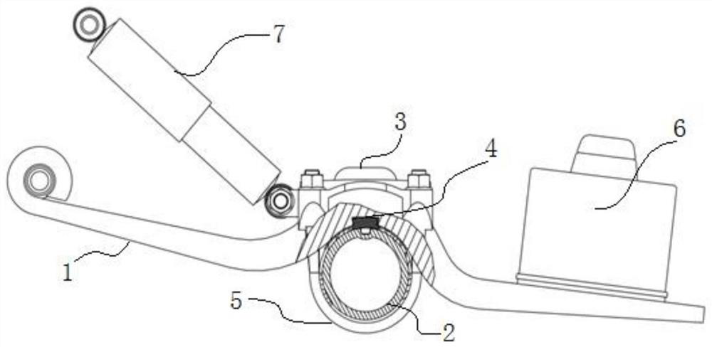
[0029] The connection mode of the automobile guide arm involved in this embodiment and the axle is as follows: figure 1 As shown, the front end of the guide arm 1 is hinged to the bracket on the frame through the rubber bushing, the shock absorber 7 is also connected to the bracket of the vehicle frame, and the rear end of the guide arm 1 is connected to the air spring base 6, and the guide arm The middle part of 1 (the part connected with the axle 2) is made into an arc shape, and the inner arc surface of the arc-shaped part matches the shape of the outer circular surface of the shaft tube of the axle 2 to be connected, so that the middle arc of the guide arm 1 can be The shape part is directly attached to the outer circular surface of the shaft tube of the axle 2, or it is fitted with an arc-shaped backing plate. The lower part uses U-shaped bolts 5 to hold up the axle tube, and finally the U-shaped bolts 5 are tightened on both ends of the pressure plate 3, so that the guid...
Embodiment 2
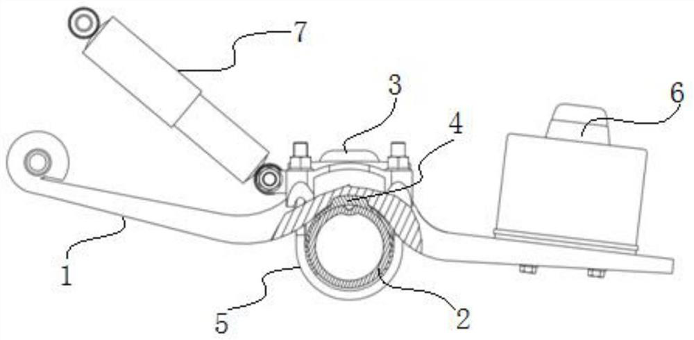
[0033] The connection mode of the automobile guide arm involved in this embodiment and the axle is as follows: figure 2 As shown, its structure and connection method are basically the same as in Embodiment 1, the difference is that the positioning block 4 in this embodiment is a backing plate with a boss, such as figure 2 As shown, the backing plate with the boss backing plate is partially embedded in the first groove, and the boss is partially embedded in the second groove, so that the vehicle is set in a rolling condition (or one side of the wheel passes the convex bag, pit), the insert provides moment to the guide arm in the longitudinal plane of the vehicle coordinate system to balance the additional moment caused by the vertical load at the front and rear ends of the guide arm due to the non-leverage ratio, that is to say, the guide arm relative to The rotational freedom of the axle around the lateral coordinate axis of the vehicle coordinate system is fully constrained, ...
Embodiment 3
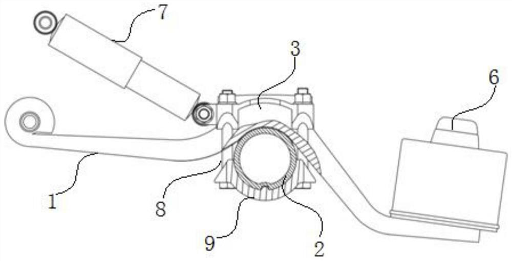
[0035] The connection mode of the automobile guide arm involved in this embodiment and the axle is as follows: image 3 As shown, the front end of the guide arm 1 is hinged to the bracket on the frame through the rubber bushing, the shock absorber 7 is also connected to the bracket of the vehicle frame, and the rear end of the guide arm 1 is connected to the air spring base 6, and the guide arm The middle part of 1 (the part connected with the axle 2) is made into an arc shape, and the inner arc surface of the arc-shaped part matches the shape of the outer circular surface of the shaft tube of the axle 2 to be connected, so that the middle arc of the guide arm 1 can be The shape part is directly attached to the outer circular surface of the shaft tube of the axle 2, or it is fitted with an arc-shaped backing plate. The lower part is provided with a supporting plate 9 to support the axle tube, and then two straight bolts 8 are used at both ends of the lower supporting plate 9 t...
PUM
 Abstract
Description
Claims
Application Information
 - R&D
- Intellectual Property
- Life Sciences
- Materials
- Tech Scout
- Unparalleled Data Quality
- Higher Quality Content
- 60% Fewer Hallucinations
Browse by: Latest US Patents, China's latest patents, Technical Efficacy Thesaurus, Application Domain, Technology Topic, Popular Technical Reports.
© 2025 PatSnap. All rights reserved.Legal|Privacy policy|Modern Slavery Act Transparency Statement|Sitemap|About US| Contact US: help@patsnap.com


