


Quick Research
Generate reliable direction feasibility study reports for your R&D in just a few steps.

Technical Q&A
Discover and master advanced knowledge NOW. Basics, ideas, possibilities, all at once.

Find Solutions
As an expert in R&D theories, this can generate solutions to your technical problems instantly.

Evaluate Feasibility
Analyze your overall solution with one click, know your potential R&D risks in advance.

Monitor Landscape
Get weekly tech updates, stay abreast of the latest tech innovations and key insights.
Continuous saw cutting device of cast ingot
A sawing device and ingot casting technology, which is applied to sawing machine devices, metal sawing equipment, metal processing equipment, etc., can solve the problems of low efficiency and inability to continuously saw ingots, so as to improve efficiency and ensure sawing effect Effect
- Summary
- Abstract
- Description
- Claims
- Application Information
AI Technical Summary
Problems solved by technology
Method used
Image

Examples
Embodiment 1
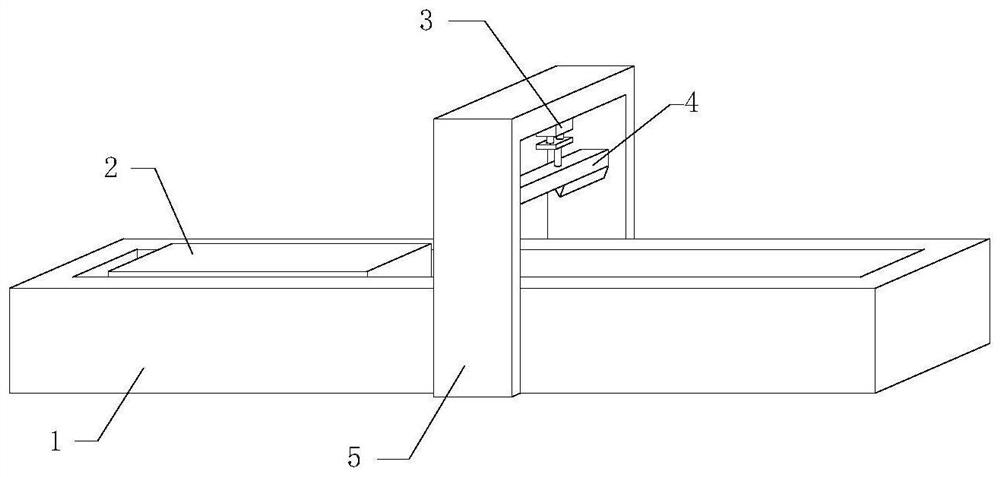
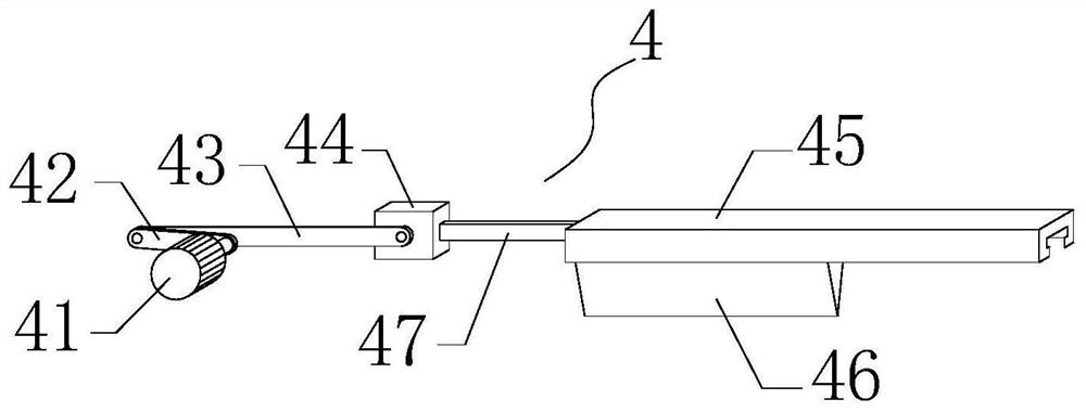
[0028] see figure 1 and figure 2 , the present invention provides a technical solution: a continuous sawing device for ingots, including a device main body, a sawing mechanism 4 and a feeding mechanism 6, and the device main body includes an underframe 1, a workbench 2, a bracket 5 and a lifting Cylinder 3, the workbench 2 is slidably connected inside the underframe 1, the bracket 5 is arranged at the middle position on the underframe 1, the cylinder is arranged on the inner top surface of the bracket 5, the sawing mechanism 4 and the lifting cylinder 3 The output shaft is fixedly connected, and the sawing mechanism 4 includes a casing 48, a motor 41, a slide rail 45, a slider 44, a sawing blade 46, a driven connecting rod 43 and a driving connecting rod 42, and the casing 48 is connected to the lifting cylinder The output shaft of 3 is fixedly connected, the motor 41 is located inside the casing 48, the slide rail 45 is arranged on the top of the casing 48, the slider 44 is...
Embodiment 2
[0031] As a preferred solution of Embodiment 1, please refer to Figure 5 , the sawing mechanism 4 also includes a drive plate 8 and a booster spring 9, the drive plate 8 is fixedly connected to the output end of the lifting cylinder 3, and the housing 48 is tightly connected to the drive plate 8 through the booster spring 9, so Several booster springs 9 are provided, and the plurality of booster springs 9 are equidistantly arranged between the transmission plate 8 and the housing 48 .
[0032] Working process: when the sawing blade 46 is in contact with the ingot, the output shaft of the cylinder continues to run, driving the booster spring 9 to shrink, and the booster spring 9 pressurizes the sawing blade 46 due to its reset force.
Embodiment 3
[0034] As another preferred solution of Embodiment 1, please refer to Figure 4 , the feeding mechanism 6 includes a transmission rod 61, a roller 62, a strip groove 63, a driver 64 and a slide table 66, the slide table 66 is fixedly connected with the workbench 2, and the lower end surfaces of the slide table 66 are equidistant A plurality of strip grooves 63 are arranged, and the driving machine 64 is arranged inside the underframe 1, and the output end of the driving machine 64 is fixedly provided with a transmission rod 61, and the end of the transmission rod 61 away from the driving machine 64 is rotatably connected. There are rollers 62 which are located inside the bar-shaped groove 63 .
[0035] The feeding mechanism 6 includes a semicircular plate and a plurality of semicircular grooves 65. A semicircular groove 65 is provided between every two bar-shaped grooves 63 on the lower end surface of the slide table 66. The semicircular plate is arranged at the output end of ...
PUM
 Abstract
Description
Claims
Application Information
 - R&D Engineer
- R&D Manager
- IP Professional
- Industry Leading Data Capabilities
- Powerful AI technology
- Patent DNA Extraction
Browse by: Latest US Patents, China's latest patents, Technical Efficacy Thesaurus, Application Domain, Technology Topic, Popular Technical Reports.
© 2024 PatSnap. All rights reserved.Legal|Privacy policy|Modern Slavery Act Transparency Statement|Sitemap|About US| Contact US: help@patsnap.com