Push rod pressing device, positioning assembly and positioning device

A technology of pressing device and push rod, which is used in transportation and packaging, space navigation equipment, space navigation aircraft, etc., can solve problems such as difficulty and high cost

Active Publication Date: 2021-12-28
TECH & ENG CENT FOR SPACE UTILIZATION CHINESE ACAD OF SCI
View PDF6 Cites 6 Cited by
  • Summary
  • Abstract
  • Description
  • Claims
  • Application Information

AI Technical Summary

Problems solved by technology

The logistics supply of the International Space Station is very expensive and difficult compared with any previous human natural exploration activities. The logistics problems faced by establishing bases on the moon and Mars in the future will be more severe, especially in response to emergencies, which are delayed by ground support The loss will be immeasurable

Method used


Image

  • Push rod pressing device, positioning assembly and positioning device
  • Push rod pressing device, positioning assembly and positioning device
  • Push rod pressing device, positioning assembly and positioning device

Examples


Embodiment 1

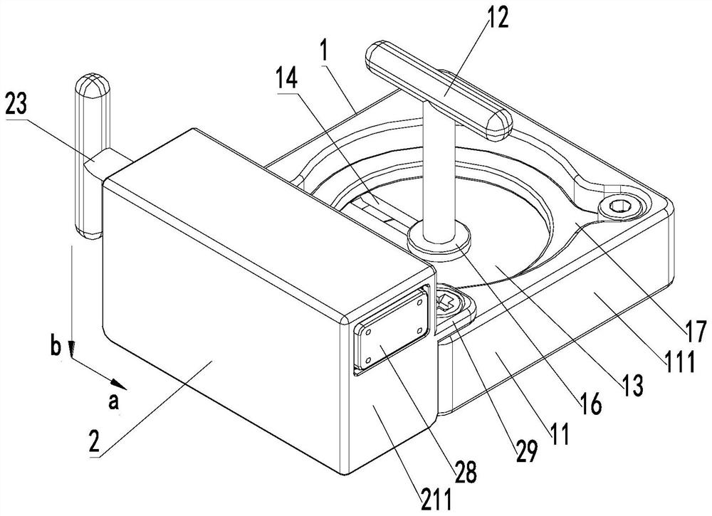
[0044] like Figure 1 ~ Figure 3 As shown, a push rod pressing device of this embodiment includes a worktable movable restraint seat 1 and a restraint head 2, and the restraint head 2 is installed on the workbench movable restraint seat 1, and the restraint head 2 The constraint direction is arranged at an angle to the installation direction of the movable constraint seat 1 of the workbench, figure 1 The direction of the middle arrow a is the constraint direction of the constraint head 2, and the direction of the arrow b is the installation direction of the movable constraint seat 1 of the workbench; the movable constraint seat 1 of the workbench includes the main support of the constraint seat, the tightening handle 12 and the movable block 13 The main support of the constraint seat is provided with an assembly through hole, and the movable stopper 13 can be embedded in the assembly through hole of the main support of the constraint seat so that it can rotate along the circum...

Embodiment 2

[0052] On the basis of Example 1, such as Figure 4 As shown, the constraining head 2 of this embodiment includes a constraining head main support, a rotating push handle 23, an elastic member, and a sliding constraining head 25. A pre-compression channel is formed in the constraining head main support, and the pre-compression channel The two ends are the operation end and the pre-compression end respectively, and the said rotary propulsion handle 23 is threadedly connected in the operation end of the said pre-compression channel and elastically connected with the sliding constraint head 25 through an elastic member; A circle of annular steps is provided on the inner sidewall (the said annular step can be a square annular step, also can be a circular annular step, or be other polygonal annular steps), and the outer sidewall of the sliding constraint head 25 is provided with an annular platform Shoulder 251, the annular shoulder 251 abuts on the annular step, and the free end o...

Embodiment 3

[0058] like Figure 5 and Image 6 As shown, a positioning assembly of this embodiment includes the push rod pressing device described in Embodiment 1 or Embodiment 2, and also includes an angle gauge 3, and the bottom of the angle gauge 3 is provided with a guide pin post 31, so that A rubber strip 32 is provided on the inner side of the angle gauge 3 . The rubber strip on the angle gauge can protect the load equipment while ensuring a certain friction. Positioning can be done on the table by setting the angle gauge to the guide pin post.

[0059] like Figure 5 and Image 6As shown, a preferred solution of this embodiment is that the inner surface of the angle gauge 3 is provided with a plurality of through grooves with the top through and the bottom closed, and rubber strips 32 are embedded in the grooves. The top of 3 is fixed with the briquetting block 33 that compresses described rubber bar 32. A pressing block can be used to compress and fix the rubber strip in th...


PUM


Abstract

The invention relates to a push rod pressing device, a positioning assembly and a positioning device. The push rod pressing device comprises a workbench movable restraining base and a restraining head, the restraining head is installed on the workbench movable restraining base, and the restraining direction of the restraining head and the installation direction of the workbench movable restraining base are arranged at an angle; the workbench movable restraining base comprises a restraining base main support, a screwing handle and a movable check block, an assembling through hole is formed in the restraining base main support, the movable check block can be embedded in the assembling through hole of the restraining base main support in the mode of rotating in the circumferential direction of the assembling through hole, and a handle sliding groove is formed in the movable check block in the radial direction; and the screwing handle is installed in the handle sliding groove and can slide along the handle sliding groove. The workbench movable restraining base and the restraining head which are arranged at an angle are adopted, the restraining head is fixed to the proper position of the workbench through the workbench movable restraining base, a pre-tightening force is provided for load equipment, and then the load equipment is restrained and fixed through a friction force generated by the restraining head and the load equipment.

Description

technical field [0001] The invention relates to the related technical field of equipment positioning in a microgravity space, in particular to a push rod pressing device, a positioning assembly and a positioning device. Background technique [0002] With the development of manned spaceflight technology, establishing a long-term habitable and working environment in outer space has become the focus of human spaceflight. The logistics supply of the International Space Station is very expensive and difficult compared with any previous human natural exploration activities. The logistics problems faced by establishing bases on the moon and Mars in the future will be more severe, especially in response to emergencies, which are delayed by ground support The loss will be immeasurable. Therefore, taking into account the initiative of astronauts, by providing personnel with a series of tools and technical support, enhancing the ability of independent maintenance and support of facili...

Claims


Application Information

Patent Timeline
Patent Type & Authority Applications(China)
IPC IPC(8): B64G1/66
CPCB64G1/66
Inventor 张璐王辅辅王珂乔志宏许莹张聚乐王乐天
Owner TECH & ENG CENT FOR SPACE UTILIZATION CHINESE ACAD OF SCI
Why Eureka
Try Eureka