
Three-dimensional simulation calculation method for multi-ring shield lining structure

A calculation method and three-dimensional simulation technology, applied in the direction of design optimization/simulation, special data processing applications, instruments, etc., can solve the problem of unrepresented shield lining bolt connection, no high versatility, and can not reflect the inner lining of single-ring segments Force distribution and other issues

Pending Publication Date: 2020-11-17
SHANGHAI TUNNEL ENGINEERING RAILWAY TRANSPORTATION DESIGN INSTITUTE
View PDF0 Cites 2 Cited by
  • Summary
  • Abstract
  • Description
  • Claims
  • Application Information

AI Technical Summary

Problems solved by technology

In the field of shield tunneling, there are currently finite element simulation calculations of shield tunneling based on the homogeneous ring method, elastic hinge method, beam-spring method, and three-dimensional plate and shell method, but the above methods have their limitations: The homogeneous ring and elastic hinge methods are mostly used in the calculation of the structural section of the shield tunnel, and cannot reflect the interaction between the longitudinal adjacent segment rings of the shield tunnel; the beam-spring method can reflect the interaction between adjacent rings , but it cannot reflect the force distribution of the lining of the single-ring segment along the longitudinal direction of the tunnel; the existing three-dimensional plate and shell law does not reflect the bolt connection between the shield lining and the shield ring
At the same time, the above methods do not have high versatility when encountering structural abnormalities such as shield tunnel openings.
Based on the limitations of the above methods, there are many difficulties in the force simulation calculation of multi-ring shield lining

Method used


Image

  • Three-dimensional simulation calculation method for multi-ring shield lining structure
  • Three-dimensional simulation calculation method for multi-ring shield lining structure
  • Three-dimensional simulation calculation method for multi-ring shield lining structure

Examples


Embodiment

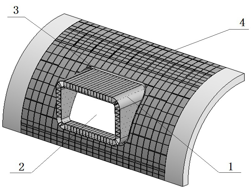
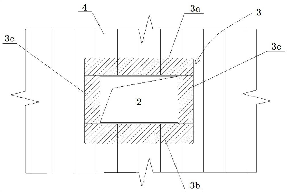
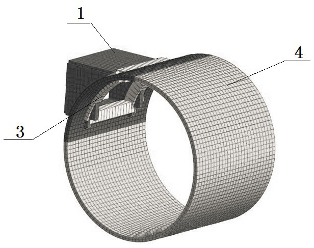
[0049] Example: such as Figure 1-6 As shown, this embodiment specifically relates to a three-dimensional simulation calculation method for a multi-ring shield lining structure. The opening 2 is located on the upper shoulder of the entire shield segment ring and is a square hole. The opening on the shield segment 3 A joint structure 3 is provided on the inner edge of the hole 2, and the joint structure 3 includes a top beam 3a at the top, a bottom beam 3b at the bottom, and arc-shaped special-shaped columns 3c on both sides; the joint structure 3 is provided with an external structure 1 , inter-ring connecting bolts 5 are used between adjacent shield segment rings, and inter-ring connecting bolts 6 are arranged between adjacent shield segment rings; the calculation method includes the following steps:

[0050] (S1) The physical geometric model is constructed by computer modeling software, which are the shield segments 4 with openings, the inter-ring connecting bolts 5 between ...


PUM


Abstract

The invention discloses a three-dimensional simulation calculation method for a multi-ring shield lining structure, and the method comprises the following steps: (S1) constructing a physical geometricmodel through computer modeling software, and the physical geometric model comprises a perforated shield segment, a non-perforated shield segment, in-ring and inter-ring connecting bolts, a joint structure, and an external structure; (S2) establishing a finite element model for the physical geometric model, and determining respective unit types and parameters; (S3) inputting load for the shield segment, the shell unit of the external structure and the beam unit of the joint structure; (S4) setting boundary conditions for the shell unit of the shield segment and the beam unit of the joint structure; and (S5) importing all units, parameters, loads and boundary conditions in the step (S1S4), and carrying out three-dimensional simulation calculation. The method has the advantages that the shield lining, the external connection structure, the perforated connection structure and the connection bolts in the rings and between the rings are respectively constructed by adopting proper units toestablish finite element simulation models for calculation, so that the stress condition of the perforated structure is effectively verified.

Description

technical field [0001] The invention belongs to the technical field of finite element simulation simulation calculation, and in particular relates to a three-dimensional simulation calculation method of a multi-ring shield lining structure. Background technique [0002] With the continuous development of the computer level, the finite element simulation calculation method is more and more widely used in the field of structural engineering. In the field of shield tunneling, there are currently finite element simulation calculations of shield tunneling based on the homogeneous ring method, elastic hinge method, beam-spring method, and three-dimensional plate and shell method, but the above methods have their limitations: The homogeneous ring and elastic hinge methods are mostly used in the calculation of the structural section of the shield tunnel, and cannot reflect the interaction between the longitudinal adjacent segment rings of the shield tunnel; the beam-spring method ca...

Claims


Application Information

Patent Timeline
IPC IPC(8): G06F30/23G06F30/13G06F119/14
CPCG06F30/23G06F30/13G06F2119/14
Inventor 陈鸿管攀峰王浩伟奚程磊胡小燕张晓菲季应伟
Owner SHANGHAI TUNNEL ENGINEERING RAILWAY TRANSPORTATION DESIGN INSTITUTE
Learn More