Eureka AIR delivers breakthrough ideas for toughest innovation challenges, trusted by R&D personnel around the world.

Method for testing sealing performance of crimping terminal assembly of crimping electric connector for cable network

A technology of crimping terminals and a testing method, which is applied in the field of tightness testing of crimping terminal components of crimping electrical connectors for cable nets, and achieves the effects of improving efficiency, increasing the number of simultaneous detections, and quickly detecting leaks.

Active Publication Date: 2020-11-17
BEIJING SATELLITE MFG FACTORY
View PDF12 Cites 4 Cited by
  • Summary
  • Abstract
  • Description
  • Claims
  • Application Information

AI Technical Summary

Problems solved by technology

[0004] The technical problem to be solved by the present invention is: to overcome the shortcomings and limitations of the prior art, to provide a method for testing the airtightness of crimped terminal assemblies of crimped electrical connectors for cable networks, and to solve the problem of the pressure resistance of copper-free aluminum composite conductors on the domestic market. Problems with special leak detection device for connector assembly and its test method and qualification criterion

Method used


Image

  • Method for testing sealing performance of crimping terminal assembly of crimping electric connector for cable network
  • Method for testing sealing performance of crimping terminal assembly of crimping electric connector for cable network
  • Method for testing sealing performance of crimping terminal assembly of crimping electric connector for cable network

Examples


Embodiment Construction

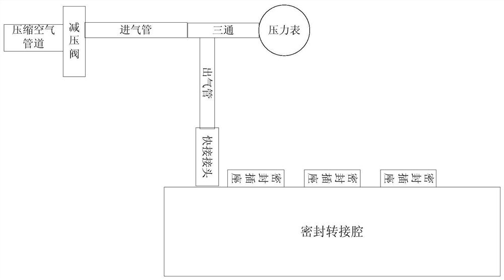
[0030] (1) Design a set of sealing test device for crimp terminal assembly

[0031] Including transparent water storage, pressure reducing valve, pressure gauge, compressed air supply pipe, tee, sealed adapter chamber, test tube fixing tool, test tube, L-shaped bracket, quick connector, sealed socket. And fix the pressure reducing valve, tee and pressure gauge on the L-shaped bracket. Connect the tightness test device to the compressed air supply pipe, and the pressure of the compressed air should not be less than 0.2MPa. Fill the water reservoir with water, the depth of water should be able to submerge the vertically placed 15ml, Φ16mm test tube and the sealed adapter chamber with a height of 80mm. It is required that the sealed transfer cavity is placed in the water storage under 0.2MPa, and there is no obvious air bubble leakage from the sealed transfer cavity. Close the compressed air valve.

[0032] Including 1 transparent water reservoir, 1 pressure reducing valve, 1 ...


PUM


Abstract

The invention discloses a method for testing the sealing performance of a crimping terminal assembly of a crimping electric connector for a cable network, and the method comprises the following steps:1) filling a water storage device with water, and putting a sealed switching cavity into the water storage device; (2) opening a compressed air pressure reducing valve, wherein it is required that noobvious bubbles leak out of a sealed through connection cavity placed in the water storage tank; 3) inserting the wire end of the crimping assembly to be detected into the mounting hole of the sealing socket on the sealing adapter cavity, and putting the sealed transfer cavity into a water storage device; 4) putting the processed contact pin or jack terminal of the crimping assembly to be detected into a test tube, inverting the opening of the test tube, emptying air in the test tube, fixing the test tube and the test tube fixing tool, and putting the test tube and the test tube fixing tool into a water storage device; 5) opening the compressed air valve again, and adjusting the pressure value of the compressed air outlet; 6) observing the plugging position of the sealing socket and the to-be-detected crimping assembly wire by naked eyes, wherein it is required that no obvious bubbles can be seen; 7) opening a stopwatch to start timing, and checking the sealing performance of the assembly; and 8) closing the compressed air pressure reducing valve, taking out the sealed adapter cavity and the test tube fixing tool from the water storage device, and pulling out the to-be-tested assembly from the sealed socket and the test tube, thereby completing the airtightness test.

Description

technical field [0001] The invention relates to a method for testing the airtightness of a crimping terminal assembly of a crimping electric connector for a cable network. Compressed air is introduced into the crimping terminal assembly, and air leakage is observed at the crimping terminal, which belongs to the technical field of electronic assembly. Background technique [0002] With the development trend of miniaturization and cost reduction of spacecraft, new requirements are put forward for the weight reduction and cost reduction of the whole satellite. Among them, the whole star cable network product is one of the important products to connect the sub-systems to realize the whole star function, and it also occupies a large weight ratio of the whole star. Therefore, weight reduction and low-cost production of the cable network to meet the application requirements of spacecraft have become urgent problems to be solved. [0003] The copper-aluminum composite metal conduct...

Claims


Application Information

Patent Timeline
Patent Type & Authority Applications(China)
IPC IPC(8): G01M3/08
CPCG01M3/08
Inventor 陈雅容郝春雨飞景明曹瑞王智彬张明华张彬彬张振明张辰华刘国玲胡慧玉
Owner BEIJING SATELLITE MFG FACTORY
Why Eureka
Eureka Blog
Learn More