High-energy-consumption-density torsional eddy current damping device and damping system

A technology of eddy current damping and damping system, which is applied in the direction of springs, magnetic springs, springs/shock absorbers, etc., can solve the problems of low energy consumption density of eddy current damping and cannot adapt to high energy consumption density, and achieve structural vibration suppression, The effect of increasing energy consumption density

Inactive Publication Date: 2020-11-17
HUNAN UNIV
View PDF7 Cites 0 Cited by
  • Summary
  • Abstract
  • Description
  • Claims
  • Application Information

AI Technical Summary

Problems solved by technology

[0005] The purpose of the present invention is to provide a torsional eddy current damping device and damping system with high energy consumption density in view of the low energy consumption density of eddy current damping in the prior art and the inability to meet the demand of high energy consumption density

Method used


Image

  • High-energy-consumption-density torsional eddy current damping device and damping system
  • High-energy-consumption-density torsional eddy current damping device and damping system
  • High-energy-consumption-density torsional eddy current damping device and damping system

Examples


Embodiment 1

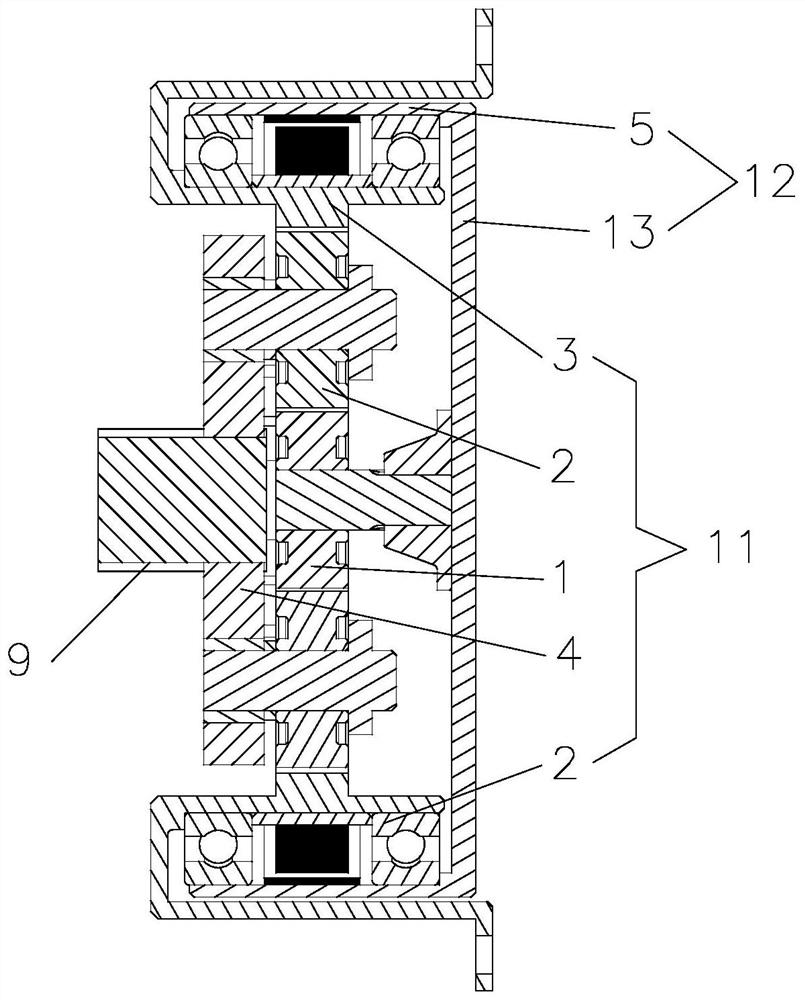
[0037] Such as Figure 1-3 As shown, a high energy consumption density torsional eddy current damping device described in this embodiment includes at least one stage of speed-up gear set 11, and also includes conductor tubes 6 that are rotatably matched with each other and magnets that are staggered along the circular direction. 7. The output end of the speed-up gear set 11 is connected to the conductor tube 6, and the speed-up gear set 11 can drive the conductor tube 6 to rotate relative to the magnets 7 arranged staggered along the circular direction. The conductor pipe 6 is sheathed on the outside of the magnets 7 arranged staggered along the circular direction, and there is a gap between the conductor pipe 6 and the magnets 7 arranged staggered along the circular direction.

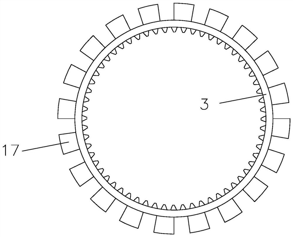
[0038]Specifically, the speed-up gear set 11 is a planetary gear mechanism, and the speed-up gear set 11 includes a planet carrier 4, a planetary gear 2, a sun gear 1 and an internal gear 3, and the m...

Embodiment 2

[0058] Such as Figure 1-4 As shown, a kind of damping system described in this embodiment includes the structure to be vibrated 14 and the high energy consumption density torsional eddy current damping device as described in Embodiment 1, the planet carrier 4 and the structure to be vibrated 14 is connected, and the internal gear 3 is connected with the structure 14 to be vibrated.

[0059] When the to-be-vibrated structure 14 generates torsional motion due to vibration or impact, it can transmit the torsional motion to the planet carrier 4, and through the speed-up effect of the planetary gear mechanism, the sun gear 1 will accelerate to rotate, thereby increasing the relative speed of the conductor tube 6 along the ring. The rotation speed of the magnets 7 arranged in a staggered direction, the conductor tube 6 moves relative to the magnets 7 arranged in a staggered direction in the ring direction in the magnetic field of the magnets 7 arranged in a staggered direction in t...


PUM


Abstract

The invention belongs to the field of vibration control, and particularly relates to a high-energy-consumption-density torsional eddy current damping device and damping system. The eddy current damping device comprises at least one stage of speed increasing gear set, conducting tubes which are in running fit with each other, and magnets which are arranged in a staggered manner along the annular direction. The output end of the speed increasing gear set is connected with the conducting tubes; and the speed increasing gear set can drive the conducting tubes to rotate relative to the magnets arranged in the staggered manner along the annular direction. According to the high-energy-consumption-density torsional eddy current damping device provided by the invention, the energy consumption density can be greatly improved, the needed damping torque is generated, the damping torque acts on an external structure so as to meet the requirement for the high energy consumption density, and the purpose of restraining structural vibration is achieved.

Description

technical field [0001] The invention belongs to the field of vibration control, and in particular relates to a high energy consumption density torsional eddy current damping device and a damping system. Background technique [0002] At present, the basic principle of eddy current damping is: when the conductor plate in the magnetic field cuts the magnetic force line, an eddy current will be generated in the conductor plate, and the eddy current will generate a new magnetic field opposite to the direction of the original magnetic field, so that there is a gap between the original magnetic field and the conductor The damping force that hinders the relative movement of the two is formed between them, and at the same time, the resistance effect of the conductor plate converts the kinetic energy obtained by the conductor plate into heat energy and dissipates it through eddy currents. If the conductor plate is connected with the vibrating structure, it can produce the effect of st...

Claims


Application Information

Patent Timeline
IPC IPC(8): F16F6/00
CPCF16F6/00
Inventor 张弘毅陈政清黄智文华旭刚牛华伟陈谨林
Owner HUNAN UNIV
Why Eureka
Try Eureka