Packaging equipment and method of polarization maintaining optical fiber butterfly-shaped laser
A technology for packaging equipment and lasers, which is applied in the direction of laser welding equipment, lasers, laser components, etc., can solve problems such as cumbersome operations, achieve the effects of simplifying the packaging process, convenient operation, and improving coupling accuracy
- Summary
- Abstract
- Description
- Claims
- Application Information
AI Technical Summary
Problems solved by technology
Method used
Image
Examples
Embodiment 1
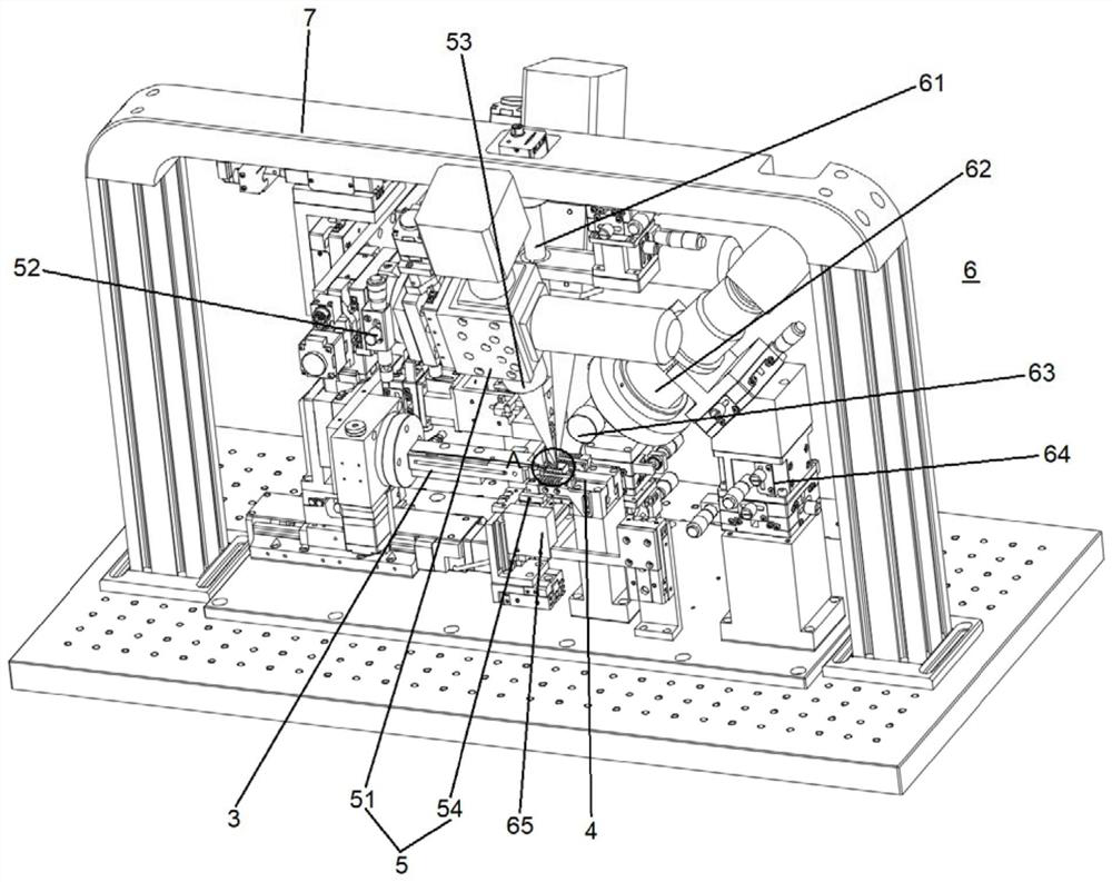
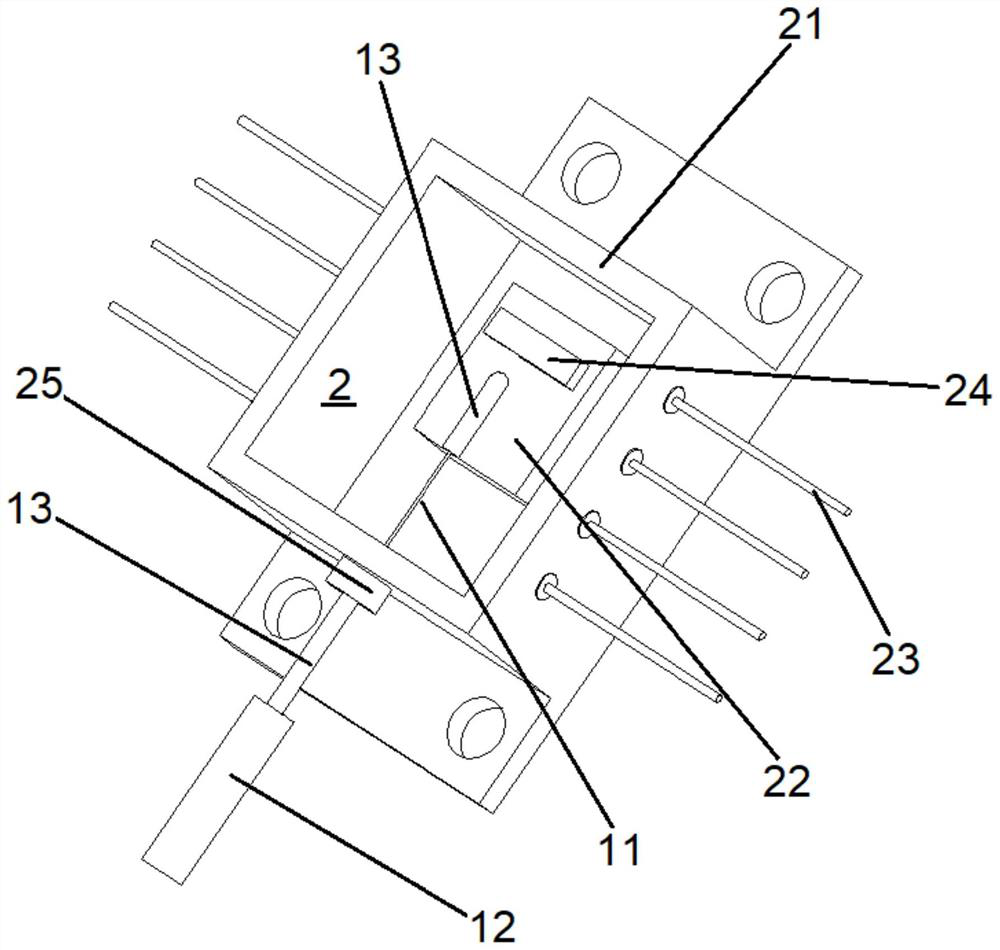
[0043] In this embodiment, the optical fiber 1 is a polarization-maintaining optical fiber, including a fiber front end 11 and a fiber tail end 12. The diameter of the fiber tail end 12 is enlarged relative to the fiber front end 11, and a metal Casing 13. The tube case 2 is butterfly-shaped and includes a bottom plate, a box body 21 arranged on the bottom plate, a heat sink 22 arranged in the box body 21 and pins 23 for power-on arranged on both sides of the box body 21. 22 is provided with a chip 24 . When packaging, the fiber front end 11 and the metal sleeve 13 here are sent to the upper surface of the heat sink 22 from the through hole 25 on one side of the box body 21 to complete the optical power and angle coupling between the optical fiber 1 and the chip 24, and then the fiber front end The metal sleeve 13 of 11 is welded to the heat sink 22, the metal sleeve 13 of the fiber end 12 is welded to the side wall of the through hole 25, and the butterfly laser as a whole c...
Embodiment 2
[0056] Embodiment 2 of the present invention provides a packaging method for a polarization-maintaining fiber butterfly laser, which can be referred to at the same time Figure 9 , including the following steps:
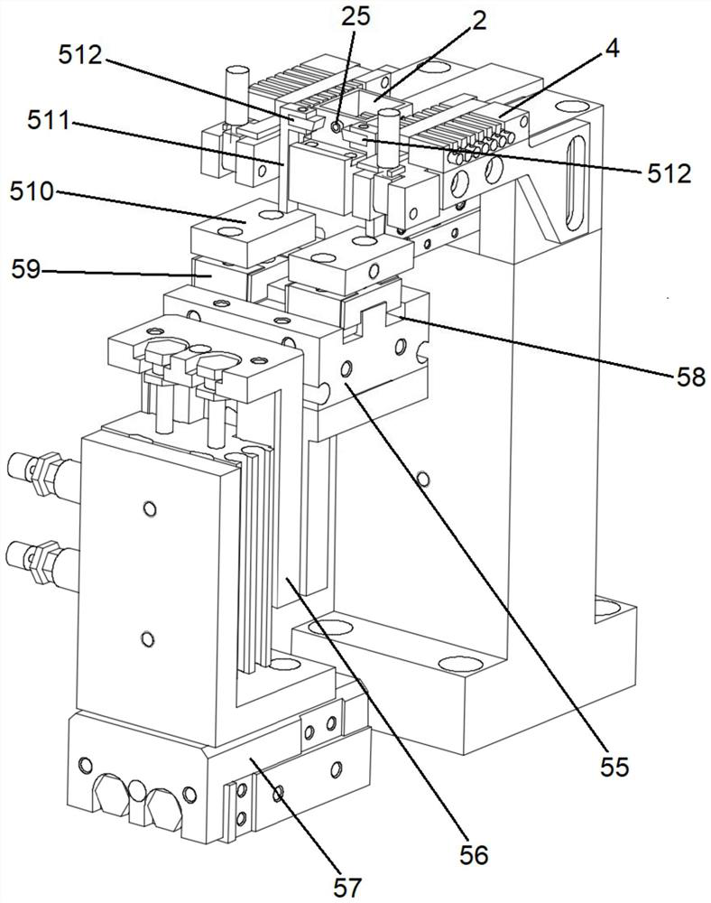
[0057] Step 1, place the shell 2 of the butterfly laser on the shell fixture module 4 to clamp and fix it, and power on the butterfly laser through the contact between the leads 46 on both sides and the pins 23, so that the chip 24 of the butterfly laser emits light , to perform optical power coupling and polarization extinction ratio (angle) coupling;
[0058] Step 2, place the optical fiber 1 on the optical fiber end clamp 35, control the optical fiber end clamp 35 so that the optical fiber 1 enters the interior of the tubular shell 2 from the through hole 25 of the tubular shell 2, and ensure that the optical fiber 1 and the metal sleeve 13 are as far as possible during this process etc. are coaxial with the through hole 25;
[0059] Step 3, when the visual moni...
PUM
 Abstract
Description
Claims
Application Information
 - R&D
- Intellectual Property
- Life Sciences
- Materials
- Tech Scout
- Unparalleled Data Quality
- Higher Quality Content
- 60% Fewer Hallucinations
Browse by: Latest US Patents, China's latest patents, Technical Efficacy Thesaurus, Application Domain, Technology Topic, Popular Technical Reports.
© 2025 PatSnap. All rights reserved.Legal|Privacy policy|Modern Slavery Act Transparency Statement|Sitemap|About US| Contact US: help@patsnap.com


