Clamp assembly for testing edge-emitting laser diode and test equipment with same

A laser diode and edge-firing technology, which is used in diode testing, optical performance testing, optical instrument testing, etc., can solve the problem of inability to ensure complete electrical contact between the component to be tested and the spring probe, failure to expose the burn-in test function, and complex mechanisms, etc. question

Pending Publication Date: 2020-11-13
致茂电子(苏州)有限公司
View PDF12 Cites 2 Cited by
  • Summary
  • Abstract
  • Description
  • Claims
  • Application Information

AI Technical Summary

Problems solved by technology

Therefore, there is no means of clamping the component under test, precise positioning of the component under test, and complete electrical contact between the component under test and the spring probe cannot be ensured
[0005] In addition, take the Chinese Patent No. CN106996990A "Test fixture for simultaneously testing multiple multi-pin laser devices" as an example, although it discloses a means of clamping the component to be tested, but The mechanism is too complicated, and it must be clamped by manually turning the handle, not to mention the function of providing a burn-in test (burn-in test) is not disclosed

Method used


Image

  • Clamp assembly for testing edge-emitting laser diode and test equipment with same
  • Clamp assembly for testing edge-emitting laser diode and test equipment with same
  • Clamp assembly for testing edge-emitting laser diode and test equipment with same

Examples


Embodiment Construction

[0019] Before the fixture assembly for testing the edge-emitting laser diode of the present invention and the testing equipment equipped with the assembly are described in detail in this embodiment, it should be noted that in the following description, similar components will use the same component symbols To represent. Moreover, the drawings of the present invention are only for illustration purposes, they are not necessarily drawn to scale, and not all details are necessarily presented in the drawings.

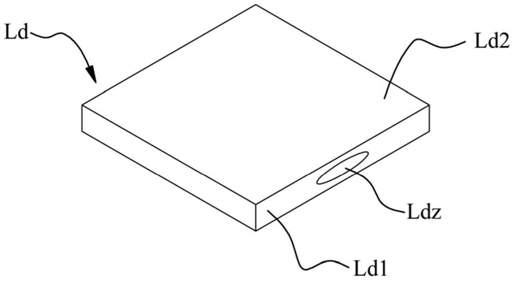
[0020] Please see first figure 1 , which is a schematic perspective view of an edge-firing laser diode Ld. Generally speaking, the edge-firing laser diode Ld includes a light-emitting surface Ld1 and a contact surface Ld2, wherein the light-emitting surface Ld1 includes a light-emitting region Ldz, that is, the laser light is emitted from the light-emitting region Ldz. In addition, a plurality of electrical contacts (not shown in the figure) are arranged on the contact sur...


PUM


Abstract

The invention relates to a clamp assembly for testing an edge-emitting laser diode and test equipment with the assembly. The clamp assembly mainly comprises a base, an upper cover and a locking mechanism. The base comprises an accommodating groove and a transmission cavity, and the transmission cavity and the accommodating groove are orthogonal and are communicated with each other; the upper covercomprises a body, a pressing block and a pressure applying assembly, the pressing block is coupled to the body and can slide relative to the body, and the pressing block is provided with an electriccontact interface; and in addition, the locking mechanism is arranged on at least one of the base and the upper cover, and selectively enables the base and the upper cover to be connected with or disconnected from each other. When the locking mechanism enables the base and the upper cover to be connected with each other, the pressure applying assembly applies force to an edge-emitting laser diodeaccommodated in the accommodating groove through the pressing block, and the edge-emitting laser diode can emit laser through the transmission cavity of the base for detection.

Description

technical field [0001] The invention relates to a fixture assembly for testing edge-emitting laser diodes and testing equipment with the assembly, especially to a fixture assembly suitable for fixing and testing edge-emitting laser diodes, and performing optical testing and electrical testing of the diodes. Test equipment for testing. Background technique [0002] Side / edge-emitting laser diode (side / edge-emitting laser diode) can be used in quite a lot of In the fields of sensing, communication, lighting, light sensing, and data storage, etc. Further explanation, such as reading and recording of CD, DVD, Blu-ray disc, photosensitive / printing of laser printer and Multi Function Peripheral (MFP), optical fiber communication, laser microscope and laser marking device, etc. , and distance sensing, smoke sensing, etc. [0003] Furthermore, whether it is portable consumer electronics or industrial application products, the trend of reducing the size of electronic equipment is ...

Claims


Application Information

Patent Timeline
Patent Type & Authority Applications(China)
IPC IPC(8): G01M11/02G01R31/26
CPCG01M11/0214G01R31/2635
Inventor J·E·霍普金斯
Owner 致茂电子(苏州)有限公司
Why Eureka
Try Eureka