Damping energy dissipation type debris flow grid dam and construction method thereof

A technology for debris flow and grid dam, applied in the field of damping energy-consuming debris flow grid dam and its construction, can solve the problems of large cross-sectional size of structural members, limited construction site, difficult material transportation, etc., to improve impact resistance, The effect of optimized impact resistance and safe and reliable structure

Active Publication Date: 2020-11-13
LANZHOU UNIVERSITY OF TECHNOLOGY
View PDF5 Cites 0 Cited by
  • Summary
  • Abstract
  • Description
  • Claims
  • Application Information

AI Technical Summary

Problems solved by technology

[0003] At present, the main problems of traditional grid dams are: (1) The design flow velocity of debris flow is considered according to the average flow velocity, which does not reflect the flow velocity of the "tongue-shaped body" presented in the evolution process, which is large in the middle and small on both sides, and the "leading" is from the top to the top. The spatial distribution characteristic of the surface flow velocity is greater than the bottom flow velocity when falling down; (2) When resisting the impact of debris flow, the structure itself consumes energy, that is, the elastic-plastic conversion or damage of component materials consumes the impact energy of debris flow, and it is necessary to strengthen the structure itself The method of strength, stiffness and ductility ensures its safety, and the cross-sectional size of the structural components is large, resulting in serious waste; (3) The complex mountainous terrain severely restricts the construction site, the transportation of materials is difficult, and the problems of long construction period and high construction difficulty are prominent

Method used


Image

  • Damping energy dissipation type debris flow grid dam and construction method thereof
  • Damping energy dissipation type debris flow grid dam and construction method thereof
  • Damping energy dissipation type debris flow grid dam and construction method thereof

Examples


Embodiment Construction

[0030] The present invention will be further explained below in conjunction with the accompanying drawings and specific embodiments. Apparently, the described embodiments are part of the embodiments of the present application, not all of them. Based on the embodiments in this application, all other embodiments obtained by persons of ordinary skill in the art without making creative efforts belong to the scope of protection of this application.

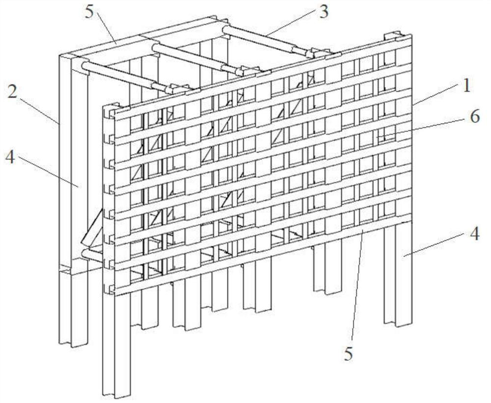
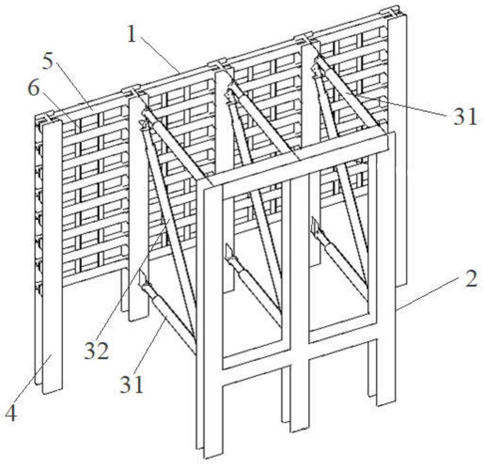
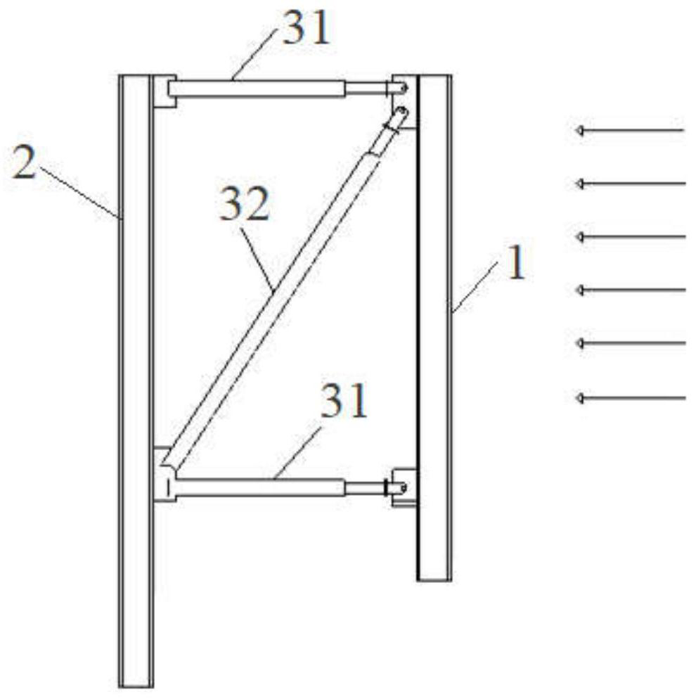
[0031] The embodiment of the present invention aims at the energy consumption of the structure itself when the traditional retaining dam resists the impact force of debris flow, and the method of enhancing the strength, stiffness and ductility of the structure itself is required to ensure its safety, which causes many defects, so a damping energy-dissipating debris flow grid is provided Barrier dams are used in the prevention and control of debris flows. Of course, the embodiments of the present invention can also be applied to hydrolog...


PUM


Abstract

The invention discloses a damping energy dissipation type debris flow grid dam and a construction method thereof. The invention aims to have stronger impact resistance, a safe and reliable structure,and small cross-sectional size of components, easy installation and disassembly, and cost saving. The damping energy dissipation type debris flow grid dam comprises a front flow surface grid structureand a back flow surface frame structure which are arranged apart and opposed to each other, and a damping component arranged between the front flow surface grid structure and the back flow surface frame structure. The damping component comprises a first damper and a second damper. The first damper is arranged horizontally. Two ends of the first damper are respectively connected with the front flow surface grid structure and the back flow surface frame structure. The second damper is arranged obliquely. Two ends of the second damper are respectively connected to the front flow surface grid structure and the back flow surface frame structure.

Description

technical field [0001] The invention relates to the field of debris flow prevention and control engineering, in particular to a damping energy-consuming debris flow grid dam and a construction method thereof. Background technique [0002] When a debris flow occurs, it carries a large amount of solid matter such as sand, stones, etc., and its volume content can reach about 13%-80%, which is extremely destructive. The grid dam can store most of the large solid matter in the debris flow, drain away the free water in the sediment, fine gravel and fluid, achieve the effect of water and rock separation, reduce the density, flow and scale of the debris flow, and reduce the downstream damage caused by the debris flow Degree. Therefore, grid dams are widely used in debris flow prevention and control projects. [0003] At present, the main problems of traditional grid dams are: (1) The design flow velocity of debris flow is considered according to the average flow velocity, which do...

Claims


Application Information

Patent Timeline
IPC IPC(8): E02B3/10F16F15/02
CPCE02B3/10F16F15/02
Inventor 王永胜吕宝宏王彦兵董旭光张世径汪文哲马强丁宏伟张国申张哓斌刘建设朱浩祝佳张岩鉴
Owner LANZHOU UNIVERSITY OF TECHNOLOGY
Why Eureka
Try Eureka