A rotary kiln for direct reduction of iron-containing materials
A rotary kiln, direct technology, applied in the field of rotary kiln, can solve the problems of low metallization rate of products, large temperature fluctuations, easy ring formation in the kiln, etc.
- Summary
- Abstract
- Description
- Claims
- Application Information
AI Technical Summary
Problems solved by technology
Method used
Image
Examples
Embodiment 1
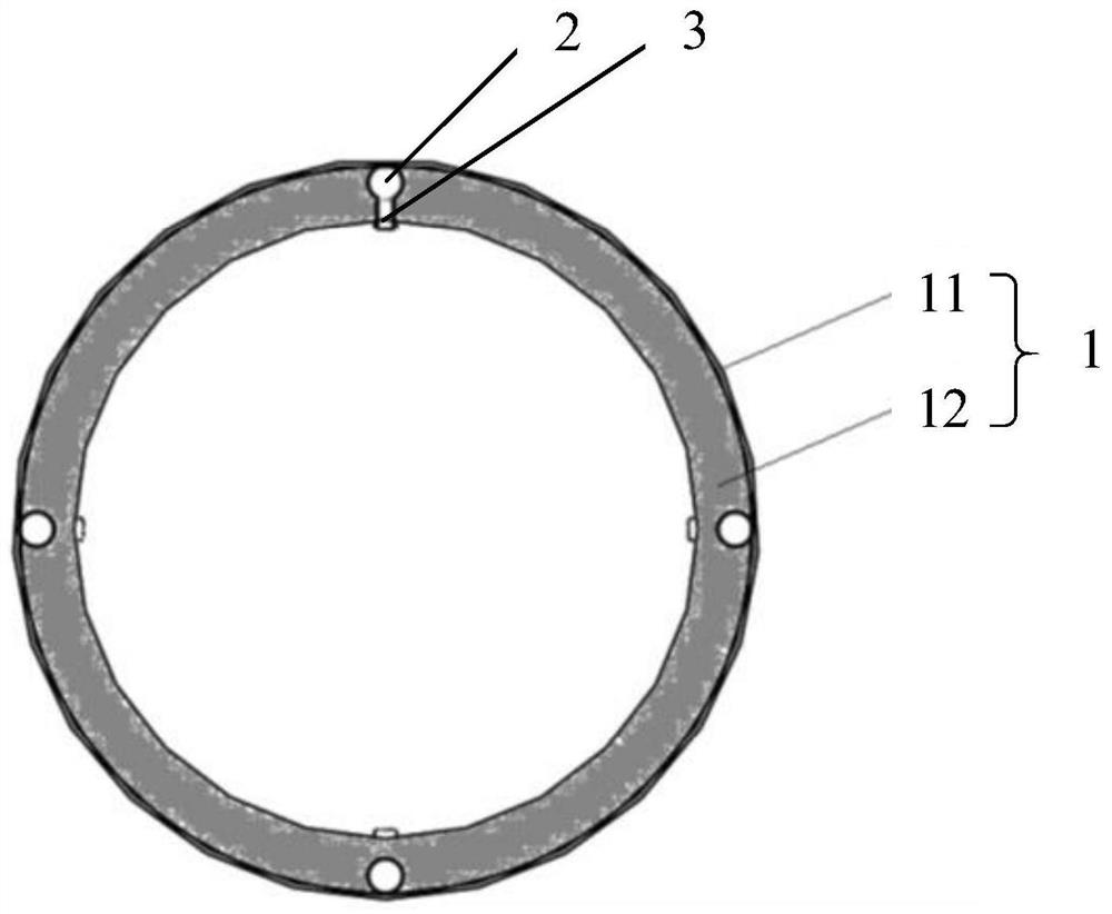
[0040] This embodiment provides a rotary kiln for direct reduction of iron-containing materials, see Figure 1 to Figure 4 , comprising a kiln body 1, an air duct 2 in the kiln and an air duct burner 3, the air duct 2 in the kiln is arranged on the inner wall of the kiln body 1 along the axial direction of the kiln body 1, and the number of the air duct burners 3 is multiple, many An air duct burner 3 is arranged on the side wall of the kiln inner air duct 2 along the axial direction of the kiln inner air duct 2, and the air duct burner 3 and the kiln inner air duct 2 are welded.
[0041] It can be understood that, in order to support the rotary kiln and realize the rotation of the rotary kiln, the above-mentioned rotary kiln also includes a drive assembly 4 (for example, a drive motor, etc.) for driving the kiln body 1 to rotate and a support assembly 5 for supporting the kiln body 1 (eg, support brackets, etc.).
[0042] During implementation, the iron-containing material a...
Embodiment 2
[0055] This embodiment provides a rotary kiln for direct reduction of iron-containing materials. Its structure is basically the same as that of the rotary kiln for direct reduction of iron-containing materials provided in Example 1. Correspondence between wind components.
[0056] Exemplarily, the air ducts 2 in the kiln are in one-to-one correspondence with the air supply components, that is to say, each air duct 2 in the kiln is equipped with a separate air supply assembly. It should be noted that during the rotation of the kiln body 1, the kiln body The lower part of 1 will be covered by iron-containing materials. At this time, the air duct burner 3 located at the lower part of the kiln body 1 cannot supply air. Therefore, the above-mentioned rotary kiln also includes a timing switch controller for controlling the timing switch of the air supply component. The device controls the air supply component to open and close periodically with the rotation of the kiln body 1, so th...
Embodiment 3
[0061] This embodiment provides a rotary kiln for direct reduction of iron-containing materials, see Figure 5 , its structure is basically the same as that of the rotary kiln for the direct reduction of iron-containing materials provided in Example 1, the difference is that there is only one air duct 2 in the kiln, and the air outlet of the air duct burner 3 extends to the axis of the kiln body 1 Location.
[0062] Compared with the prior art, the beneficial effect of the rotary kiln for direct reduction of iron-containing materials provided in this embodiment is basically the same as that of the rotary kiln for direct reduction of iron-containing materials provided in Example 1, and will not be repeated here.
[0063] In addition, the number of air duct 2 in the kiln is one, and the air outlet hole of the air duct burner 3 is extended to the axis position of the kiln body 1, and the supporting gas radiates outward from the center position in the kiln, which can ensure the te...
PUM
 Abstract
Description
Claims
Application Information
 - R&D
- Intellectual Property
- Life Sciences
- Materials
- Tech Scout
- Unparalleled Data Quality
- Higher Quality Content
- 60% Fewer Hallucinations
Browse by: Latest US Patents, China's latest patents, Technical Efficacy Thesaurus, Application Domain, Technology Topic, Popular Technical Reports.
© 2025 PatSnap. All rights reserved.Legal|Privacy policy|Modern Slavery Act Transparency Statement|Sitemap|About US| Contact US: help@patsnap.com


