Laser repair device

A laser repair and laser emission technology, applied in laser welding equipment, welding equipment, metal processing equipment, etc., can solve the problems of inability to adjust the size of the laser beam spot, unsatisfactory repair effect, burning effect, etc., to avoid the laser size Oversize, reduce thermal effects, improve the effect of repair accuracy

Inactive Publication Date: 2020-11-13
苏州科韵激光科技有限公司
View PDF10 Cites 1 Cited by
  • Summary
  • Abstract
  • Description
  • Claims
  • Application Information

AI Technical Summary

Problems solved by technology

[0004] Since the spot size of the laser beam cannot be adjusted by scanning, when repairing a certain pixel of the display screen, when the spot size of the laser beam is too large, it is easy to cause other pixels around the pixel to be affected by the burning of the laser beam. Cause damage, poor repair effect

Method used


Image

  • Laser repair device
  • Laser repair device
  • Laser repair device

Examples


Embodiment Construction

[0032] In order to make the technical problems solved by the embodiments of the present invention, the technical solutions adopted and the technical effects achieved clearer, the technical solutions of the present invention will be further described below in conjunction with the accompanying drawings and through specific implementation methods. It should be understood that the specific embodiments described here are only used to explain the present invention, but not to limit the present invention. In addition, it should be noted that, for the convenience of description, only parts related to the present invention are shown in the drawings but not all content.

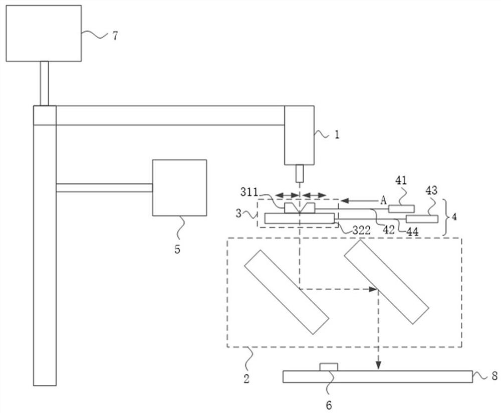
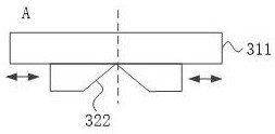
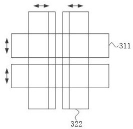
[0033] figure 1 It is a structural schematic diagram of a laser repair device provided by an embodiment of the present invention, figure 2 is attached figure 1 Schematic diagram of the slit structure in the A direction, such as figure 1 and figure 2 As shown, a laser repair device includes: a laser emitter 1, a l...


PUM

PropertyMeasurementUnit
thicknessaaaaaaaaaa

Abstract

The invention provides a laser repair device. The laser repair device comprises a laser emitter, a light guiding assembly and a slit structure. The slit structure comprises a first group of light blocking sheets and a second group of light blocking sheets which are overlaid on the laser emitting path. The first group of light blocking sheets comprises two first light blocking sheets which are located on the same plane and can oppositely move. The second group of light blocking sheets comprise two second light blocking sheets which are located on the same plane and can oppositely move. The twofirst light blocking sheets form a first slit. The two second light blocking sheets form a second slit. The first slit and the second slit intersect. The intersection point of the first slit and the second slit is located on the laser emitting path. The slit structure is used for allowing the laser beam emitted by the laser emitter to pass through and controlling the radial dimension of the laserbeam. The laser repairing device can effectively control the size of the spot of the laser, improve the repair accuracy and prevent pixels around a repaired area from being damaged.

Description

technical field [0001] Embodiments of the present invention relate to the technical field of repairing display screens, in particular to a laser repairing device. Background technique [0002] In the display industry, the production of liquid crystal display panels (LCD for short) often produces some defects such as bright spots, flash points, and broken spots. [0003] In the prior art, aiming at defects in the production process of LCD display screens, a film layer of LCD products is usually carbonized by means of vibrating mirror scanning (Direct Method, DM process for short), and the high heat generated by the laser beam is used to oxidize The indium tin layer is carbonized layer by layer to achieve the purpose of removing the defects of the display screen. [0004] Since the spot size of the laser beam cannot be adjusted by scanning, when repairing a certain pixel of the display screen, when the spot size of the laser beam is too large, it is easy to cause other pixels...

Claims


Application Information

Patent Timeline
Patent Type & Authority Applications(China)
IPC IPC(8): B23K26/073B23K26/70
CPCB23K26/073B23K26/702
Inventor 郝帅董岱杨军
Owner 苏州科韵激光科技有限公司
Why Eureka
Try Eureka