A medical device based on high power semiconductor laser

A medical device and semiconductor technology, which is applied in the direction of semiconductor laser devices, semiconductor lasers, and structural details of semiconductor lasers, can solve the problems of long cooling and heat dissipation paths, increased volume and weight, and difficulties in treating personnel, and achieve light weight, Effect of high energy density and volume reduction

Active Publication Date: 2018-05-25
FOCUSLIGHT TECH
View PDF8 Cites 0 Cited by
  • Summary
  • Abstract
  • Description
  • Claims
  • Application Information

AI Technical Summary

Problems solved by technology

[0004] First of all, the structural design of the water circulation system and refrigeration system of the current product has the problem that the cooling path and heat dissipation path are too long
[0005] Secondly, the optical system of current products mostly adopts the form of one optical waveguide, optical waveguide plus window glass, or two sections of optical waveguide. Although this can also achieve the purpose of uniform light spot output, the optical waveguide often has to be lengthened in order to achieve uniform light spot. The length of the product increases the volume and weight of the
This will cause certain difficulties for the treatment personnel during treatment. Holding heavy objects for a long time will cause soreness and swelling in the hands, which will affect the treatment effect.
[0006] In addition, the light source part of the existing products is mostly exposed, and external factors have a great impact on the laser, such as dust, etc., and the condensation phenomenon of the product itself will also have a serious impact on the laser

Method used


Image

  • A medical device based on high power semiconductor laser
  • A medical device based on high power semiconductor laser
  • A medical device based on high power semiconductor laser

Examples


Embodiment Construction

[0046] 1. Light source

[0047] The present invention can adopt high-power semiconductor laser arrays (the power can reach 1500W in an instant), and the energy density required for treatment can be realized with a relatively small pulse width.

[0048] 1) Optical system

[0049] a. Optical scheme

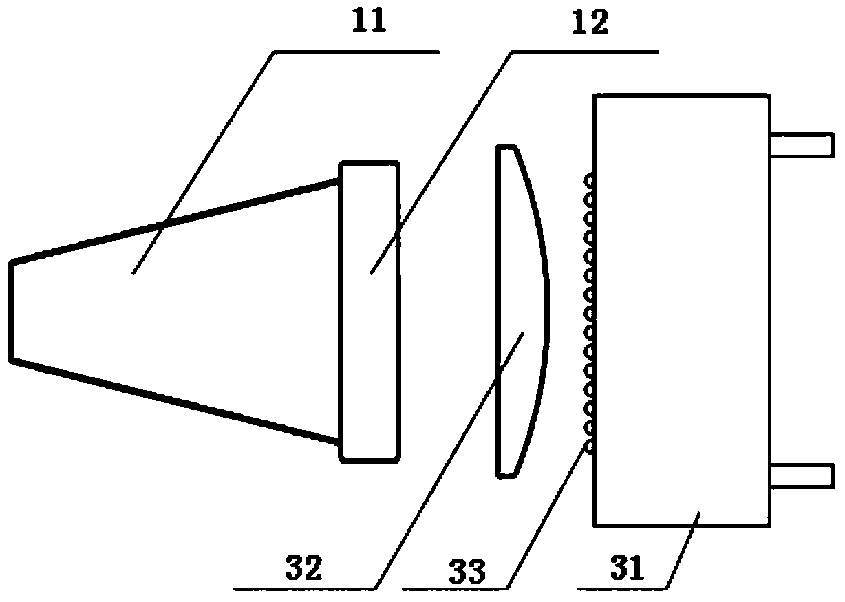
[0050] The optical system consists of a D-type lens, a plano-convex cylindrical mirror, a plano-concave cylindrical mirror, and a sapphire optical waveguide, such as figure 2 , image 3 As shown, the role played in the optical system is:

[0051] ① D-type lens: fast-axis compression for each row of light-emitting units of the laser;

[0052] ②Fast-axis mirror (plano-convex cylindrical mirror): perform fast-axis compression on the whole beam after the beam shaping by the D-shaped lens;

[0053] ③Slow-axis mirror (plano-concave cylindrical mirror): slow-axis compression is performed on the light beam compressed by the fast axis;

[0054] ④Sapphire optical waveguide: Finally, thro...


PUM


Abstract

The invention provides a medical device based on a high-power semiconductor laser. The size and the weight of a product are greatly reduced; and the stable work at high power is ensured. The medical device comprises an optical shaping system, an optical waveguide, an optical waveguide fixing element, a TEC and a water treating structure element, wherein the whole body of the water treating structure element is provided with a center-through cavity in the direction along an optical axis; a circulation water passage is arranged inside a body of the water treating structure element; a semiconductor laser stack array is accommodated and fixed in a cavity formed in the back part of the water treating structure element; a cavity formed in the front part of the water treating structure element forms the position limitation on one lens arranged in the optical shaping system; a lens press plate is arranged at the front end surface or the back end surface of the lens in parallel; a region, corresponding to a light transmission region of the lens, of the lens press plate is hollow; the lens press plate is matched with the corresponding sealing element for sealing a gap between the lens and the water treating structure element; the cold end of the TEC is attached to the back end surface of the optical waveguide fixing element and is installed and fixed; and the hot end of the TEC is attached to the front end surface of the water treating structure element and is installed and fixed.

Description

technical field [0001] The invention relates to a semiconductor laser medical device. Background technique [0002] At present, medical devices based on semiconductor lasers are generally composed of light sources, optical systems, water circulation systems, and refrigeration systems, such as figure 1 shown. [0003] Most of the light sources of existing products use low-power or medium-power semiconductor laser arrays. In the QCW treatment mode, a large pulse width is required to achieve the energy density necessary for treatment and to achieve the therapeutic effect. The pulse width is relatively large, and the user will feel obvious pain and even burns during treatment. The reason why it is rare to see the use of high-power semiconductor laser stacks as the light source is not only the cost factor, but also the consideration of the volume and weight of the product. [0004] First of all, the structural design of the water circulation system and refrigeration system of ...

Claims


Application Information

Patent Timeline
Patent Type & Authority Patents(China)
IPC IPC(8): A61B18/20A61N5/067H01S5/024H01S5/02H01S5/40
CPCA61B18/20A61N5/06H01S5/02H01S5/024H01S5/40
Inventor 关鹏蔡磊郑艳芳李英杰戴晔刘兴胜
Owner FOCUSLIGHT TECH
Why Eureka
Try Eureka