
Laser focusing device and method for laser focusing

A focusing device and laser technology, applied in laser welding equipment, welding equipment, metal processing equipment, etc., can solve problems such as difficult to accurately control the size of welding points, short service life of welding devices, inconsistent heating of optical materials, etc., and achieve no tool loss , prolong service life, good cutting effect

Inactive Publication Date: 2019-10-08
HARBIN UNIV OF SCI & TECH
View PDF6 Cites 0 Cited by
  • Summary
  • Abstract
  • Description
  • Claims
  • Application Information

AI Technical Summary

Problems solved by technology

[0007] The purpose of the present invention is to solve the problems of short service life of the existing welding device, uneven light irradiation during the welding process, inconsistent heating of optical materials, and difficulty in accurately controlling the size of the welding spot, and to provide a laser focusing device and a laser focusing method thereof

Method used


Image

  • Laser focusing device and method for laser focusing
  • Laser focusing device and method for laser focusing
  • Laser focusing device and method for laser focusing

Examples


specific Embodiment approach 1

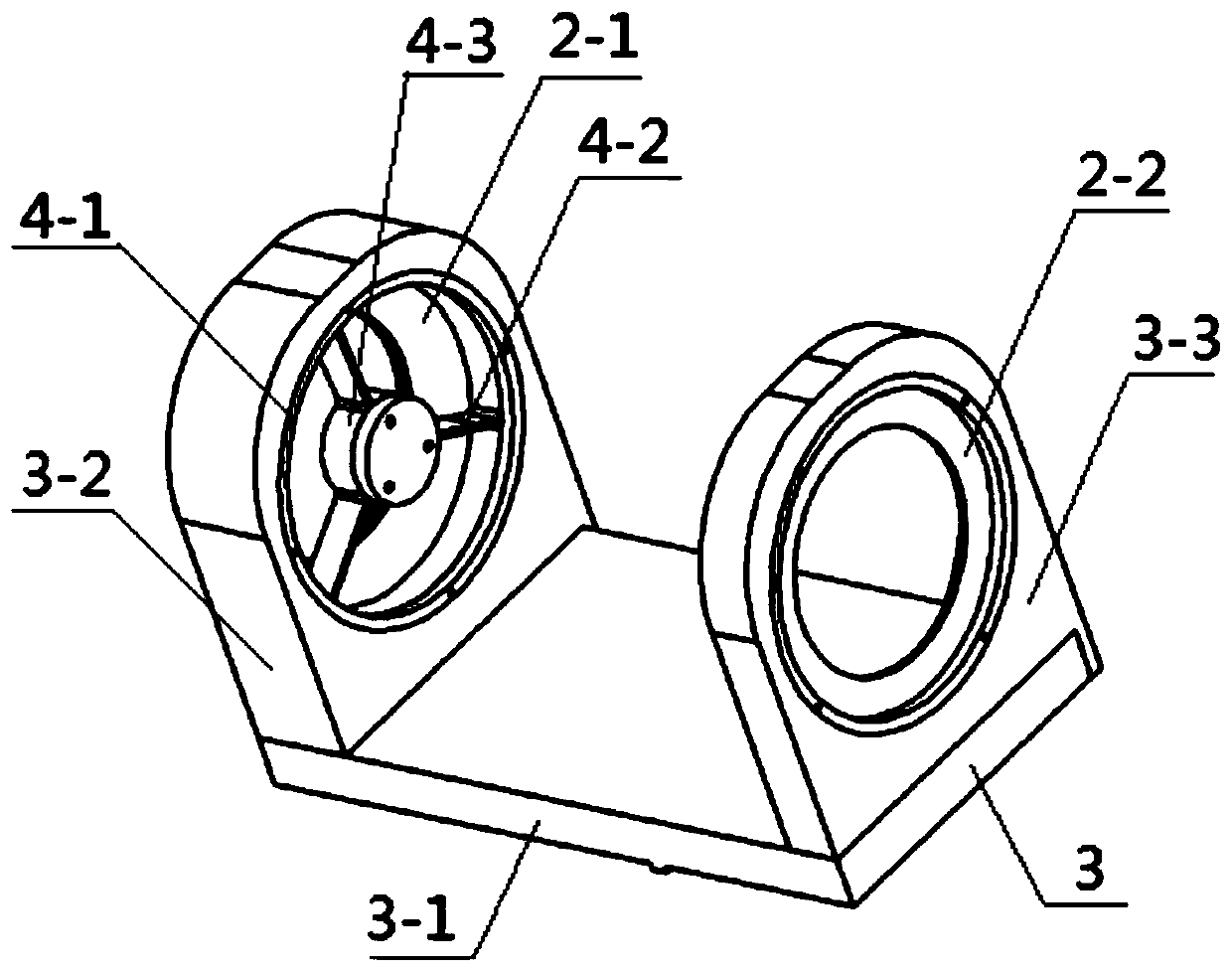
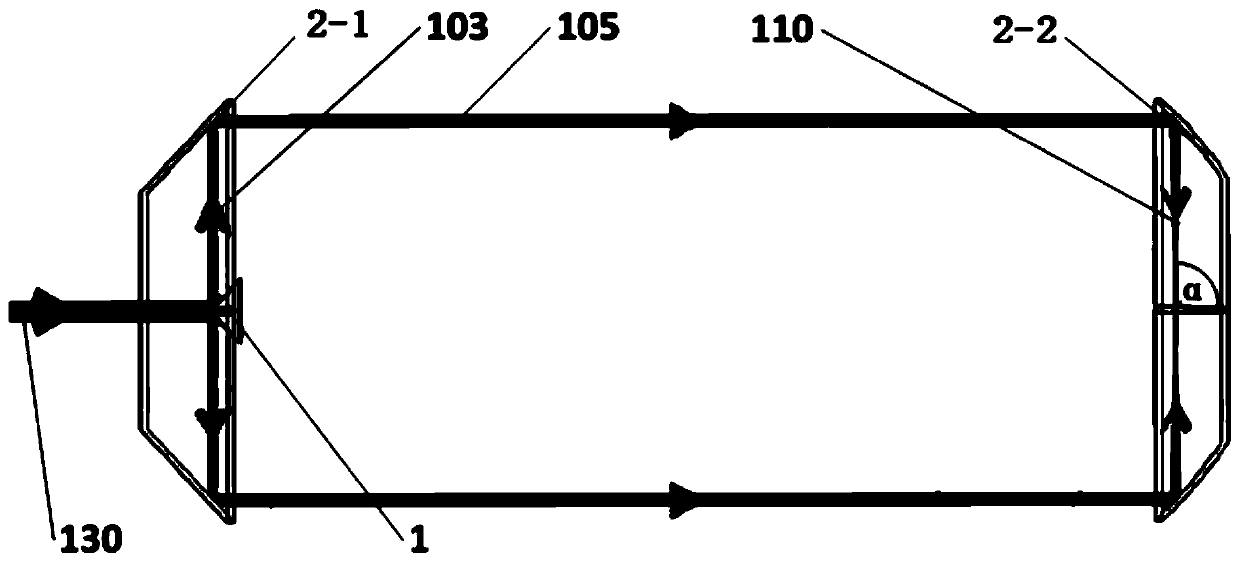
[0044] Specific implementation mode one: combine figure 1 and 2 Describe this embodiment in detail, a laser focusing device in this embodiment includes a total reflection light cone 1, a first total reflection mask 2-1, a second total reflection mask 2-2, a support device 3 and a ring bracket;

[0045]The annular bracket includes a first circular side wall 4-1, a connecting piece 4-2 and a second circular side wall 4-3, and the second circular side wall 4-3 is concentrically fixed on the Inside the first circular side wall 4-1;

[0046] The support device 3 includes a base 3-1, a first support part 3-2 and a second support part 3-3, and the first support part 3-2 and the second support part 3-3 are respectively located on the left and right sides of the base 3-1;

[0047] The first support part 3-2 is provided with a first installation hole, the second support part 3-3 is provided with a second installation hole, and the inside of the first installation hole along the laser ...

specific Embodiment approach 2

[0060] Specific implementation mode two: combination Figure 10 The difference between this embodiment and the first embodiment is that: the second circular side wall 4-3 is also provided with a laser entrance and a The central axis between the laser outlets of the first total reflection mask 2-1 reciprocates the voice coil motor 4-4, and the total reflection light cone 1 is arranged on the mover of the voice coil motor 4-4. Others are the same as the first embodiment.

[0061] The voice coil motor 4-4 described in this specific embodiment drives the total reflection light cone 1, and can move along the path between the laser entrance of the first total reflection mask 2-1 and the laser exit of the first total reflection mask 2-1. Reciprocating motion on the central axis between.

[0062] The second circular side wall 4-3 of the annular support in this specific embodiment is not directly fixed and equipped with a total reflection light cone 1, but is equipped with a voice co...

specific Embodiment approach 3

[0063] Embodiment 3: The difference between this embodiment and Embodiment 1 or 2 is that the front end of the total reflection light cone 1 is made of an aluminum reflector or a reflector coated with a reflective film. Others are the same as those in Embodiment 1 or 2.

[0064] According to different laser beam types in this specific embodiment, the total reflection light cone 1 can be classified into aluminum reflectors or reflective film-coated reflectors.


PUM

PropertyMeasurementUnit
Cone angleaaaaaaaaaa
Diameteraaaaaaaaaa
Diameteraaaaaaaaaa

Abstract

The invention relates to a laser focusing device and a method for laser focusing through the laser focusing device, and belongs to the technical field of optical fiber welding and laser welding. The problems that an existing welding device is short in service life, light irradiation is uneven in the welding process, optical materials are inconsistent in heating, and the size of welding points is difficult to control accurately are solved. The laser focusing device comprises a total reflection light cone, a first total reflection photomask, a second total reflection photomask, a support deviceand a ring bracket. The method comprises the steps that external laser beams are directly incident on the front end of the total reflection cone, scattered laser beams are reflected to the inner ringsurface of the first total reflection photomask, the scattered laser beams are converged into parallel laser beams through a 45-degree reflection ring mirror on the inner ring surface of the first total reflection photomask, the parallel laser beams are converged to a focal point of the second total reflection photomask through a hollow focusing ring mirror on the inner surface of the second totalreflection photomask, or a focusing angle alpha formed by converging the parallel laser beams to the focal point of the second total reflection photomask is adjusted through a voice coil motor.

Description

technical field [0001] The invention belongs to the technical field of laser welding. Background technique [0002] As a new type of communication, optical fiber communication plays an increasingly important role in the field of scientific and technological production. Compared with traditional electrical signals, optical fiber communication can transmit large amounts of information at ultra-high speed without loss. [0003] However, on the one hand, because the length of a coil of optical fiber in actual production is generally within a certain range, if the communication distance exceeds the maximum optical fiber length, it is inevitable to fuse multiple coils of optical fiber together; The unit energy density output from the high-power and high-energy laser to the end face of the fiber is too high, which may easily cause damage to the output end face. Therefore, in order to avoid burning the output end of the fiber, a quartz end cap will be welded on the end face of the ...

Claims


Application Information

Patent Timeline
IPC IPC(8): B23K26/046B23K26/06B23K26/21
CPCB23K26/046B23K26/0643B23K26/21
Inventor 王暄张全齐轩
Owner HARBIN UNIV OF SCI & TECH
Learn More