High speed wire package type neatening equipment and control method thereof

A control method and regular technology, applied in the field of steel rolling, can solve the problem of easy occurrence of floating wire and other problems

Pending Publication Date: 2020-11-13
ZENITH STEEL GROUP CORP +1
View PDF0 Cites 3 Cited by
  • Summary
  • Abstract
  • Description
  • Claims
  • Application Information

AI Technical Summary

Problems solved by technology

[0003] The technical problem to be solved by the present invention is: to solve the technical problem that floating wires are easy to appear on the outside of the traditional high-wire finished product

Method used


Image

  • High speed wire package type neatening equipment and control method thereof
  • High speed wire package type neatening equipment and control method thereof
  • High speed wire package type neatening equipment and control method thereof

Examples


Embodiment 1

[0035] Embodiment 1: A control method for high wire package shape regulation, which is used for Φ5.5mm welding wire steel, comprising the following steps:

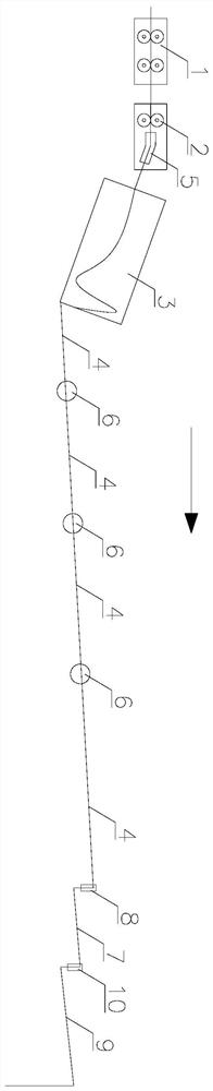
[0036] S1, adjust the angle of the left supporting plate 34, its adjustment range is 20 ° ~ 30 °, adjust the height of the lower supporting plate 35, its adjustment range is 10 ° ~ 20 °, adjust the height of the right supporting plate 36, its adjustment range is 20°~30°, raise the height of the first cooling roller table 4 adjacent to the laying head 3, and the lifting range is 60mm~80mm;

[0037] S2. Adjust the distance between the first vertical roller 8 and the second vertical roller 10, between 1080mm and 1090mm;

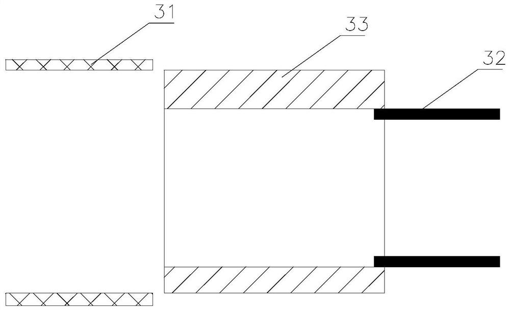
[0038] S3. Adjust the gap between the deflector plate 31 and the split plate 37, between 2.5mm and 3.5mm;

[0039] S4, adjust the speed of the laying head 3 so that the speed of the laying head 3 is 0.5m / s smaller than the speed of the finishing mill 1;

[0040] S5. Adjust the spinning machine 3 so that th...

Embodiment 2

[0043] Embodiment 2: A control method for high wire wrap shape regulation, which is used for Φ6.5mm cold heading steel, including the following steps:

[0044] S1, adjust the angle of the left supporting plate 34, its adjustment range is 15 ° ~ 25 °, adjust the height of the lower supporting plate 35, its adjustment range is 5 ° ~ 15 °, adjust the height of the right supporting plate 36, its adjustment range is 15°~25°, the height of the first cooling roller table 4 adjacent to the laying head 3 is raised, and the lifting range is 70mm~90mm;

[0045] S2. Adjust the distance between the first vertical roller 8 and the second vertical roller 10, between 1085mm and 1095mm;

[0046] S3. Adjust the gap between the deflector plate 31 and the split plate 37, between 2.5 mm and 4 mm;

[0047] S4, adjust the speed of the laying head 3 so that the speed of the laying head 3 is 0.5m / s smaller than the speed of the finishing mill 1;

[0048] S5. Adjust the spinning machine 3 so that the...


PUM


Abstract

The invention discloses high speed wire package type neatening equipment including a finishing mill, a pinch roll, a spinning machine and a plurality of first cooling roll tables which are arranged successively. The first cooling roll tables are located below an exit of the spinning machine, a bending guide is arranged between the pinch roll and the spinning machine, the upper wall of an inner hole of the bending guide is in an arc shape, the spinning machine is provided with a deviation guiding plate and a spinning pipe arranged successively, a flow guiding groove is formed between the deviation guiding plate and the spinning pipe, one end of the spinning pipe is located in the flow guiding groove, the upper wall of an inner hole of the flow guiding groove is in an arc shape, a split plate is arranged on the outer side of the deviation guiding plate, a gap is arranged between the deviation guiding plate and the split plate, and a left carrying plate, a lower carrying plate and a rightcarrying plate are arranged on the lower half position in the split plate. The bending guide and the flow guiding groove make high speed wires move directionally and an only wire channel is formed inthe process of the spinning machine, the arrangement of the left carrying plate, the lower carrying plate and the right carrying plate can improve the stability of the falling of the high speed wires, the height of a first section of the first cooling roll table is adjusted, and bounce generated in the falling of coils can be eliminated, so that the problem that a high speed wire package type isprone to generate floating silk can be solved.

Description

technical field [0001] The invention relates to the technical field of steel rolling, in particular to a high-wire wrap type regularizing device and a control method thereof. Background technique [0002] The package quality of High Line reflects the control level of High Line collection and directly affects the potential competitiveness of the market. With the upgrading of rolling equipment and the increase of final rolling speed, when continuously producing Φ≤8mm slow-cooled steel, intermittent floating wires ranging from several to hundreds of turns are likely to appear on the outer side of the high-wire finished product, that is, convex In the process of transshipment and transportation, the deformed flying wire coils after packaging are prone to pulling, breaking or knotting, which will increase the processing failure rate and processing cost of downstream customers. Contents of the invention [0003] The technical problem to be solved by the present invention is: to...

Claims


Application Information

Patent Timeline
Patent Type & Authority Applications(China)
IPC IPC(8): B21B41/00
CPCB21B41/00
Inventor 李伟张黎明刘海斌
Owner ZENITH STEEL GROUP CORP
Why Eureka
Try Eureka