
Modeling method of flux linkage adjustable permanent magnet synchronous reluctance motor

A reluctance motor, permanent magnet synchronous technology, applied in design optimization/simulation, special data processing applications, etc., can solve the efficiency optimization operation difficulty of permanent magnet synchronous reluctance motor, affect the motor loss and operation efficiency, and affect the motor control model. accuracy, etc.

Active Publication Date: 2020-11-10
SOUTHEAST UNIV
View PDF3 Cites 10 Cited by
  • Summary
  • Abstract
  • Description
  • Claims
  • Application Information

AI Technical Summary

Problems solved by technology

However, this method of offline motor model correction is difficult to take into account the real-time influence of factors such as temperature changes and loss current, which in turn affects the accuracy of the motor control model, and some complex offline motor electromagnetic analysis cannot be directly used for real-time motor control. Limits the improvement of motor control performance
In addition, the AC / DC axis current components of permanent magnet synchronous reluctance motors are tightly coupled, and the current components participate in the motor torque generation and magnetic field regulation at the same time, which in turn affects the motor loss and operating efficiency. In addition, the commonly used NdFeB permanent magnets have low magnetic adjustment efficiency , which brings difficulties to the efficiency-optimized operation of permanent magnet synchronous reluctance motors in a wide speed range

Method used

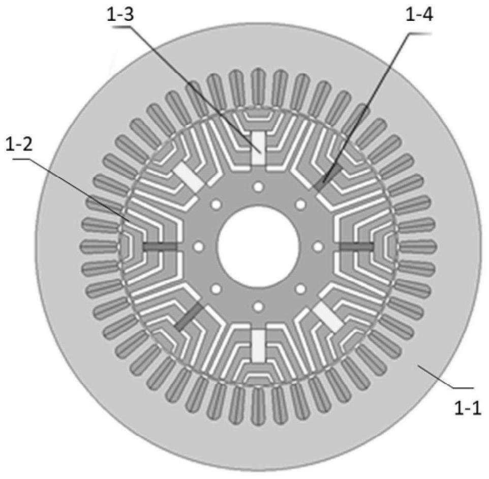
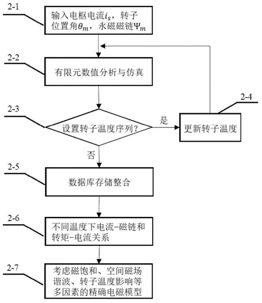
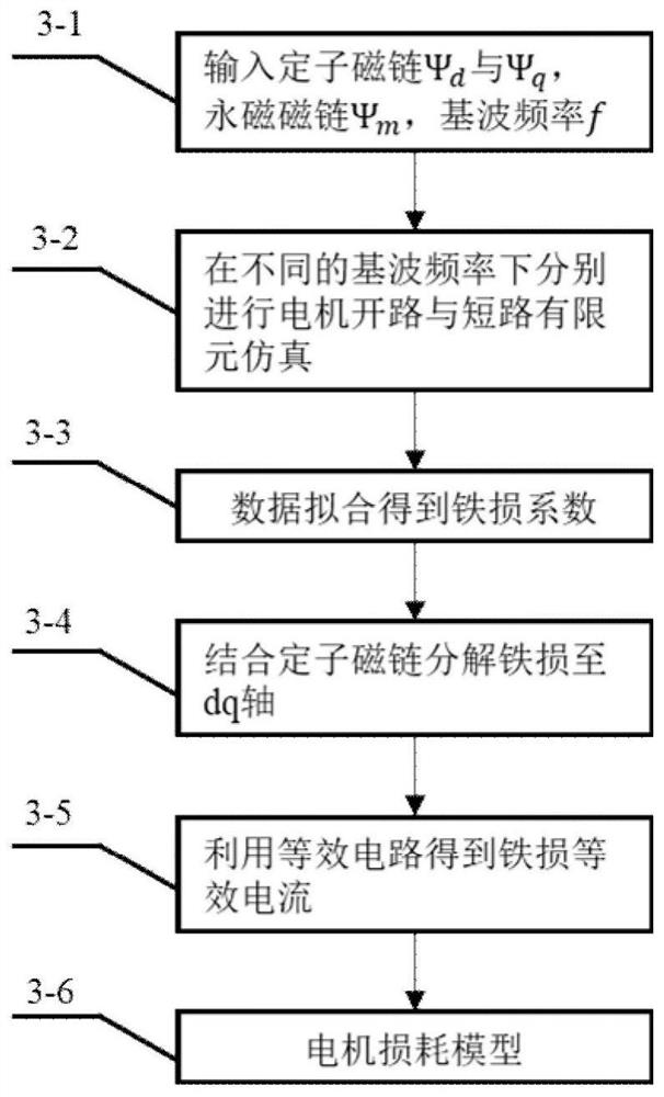

Image

  • Modeling method of flux linkage adjustable permanent magnet synchronous reluctance motor
  • Modeling method of flux linkage adjustable permanent magnet synchronous reluctance motor
  • Modeling method of flux linkage adjustable permanent magnet synchronous reluctance motor

Examples


Embodiment Construction

[0052] Embodiments of the invention are described in detail below, examples of which are illustrated in the accompanying drawings. The embodiments described below by referring to the figures are exemplary only for explaining the present invention and should not be construed as limiting the present invention.

[0053] The present invention provides an accurate modeling method for flux-linkage adjustable permanent magnet synchronous reluctance motor, aiming at the inability to calculate the influence of temperature change and loss current in the aforementioned existing motor model and the off-line electromagnetic analysis is too complicated to be used for real-time control To solve the problem, the precise motor modeling method proposed by the present invention can fully include the influence of temperature changes and loss current on the real-time operating conditions of the motor during operation, thereby improving the accuracy of the motor model. At the same time, the precise...


PUM


Abstract

The invention discloses a modeling method of a flux linkage adjustable permanent magnet synchronous reluctance motor. The method comprises the following steps: extracting relation data of change of motor stator flux linkage and electromagnetic torque along with armature current and rotor position angle through finite element modeling analysis, solving an inverse function through a pair flux-current relationship function, constructing an armature current database taking stator flux linkage and rotor angle as parameter variables and an electromagnetic torque database taking armature current androtor angle as parameter variables, and further obtaining change rate data of the armature current and the electromagnetic torque of the motor along with the temperature through finite element analysis at different temperatures. Meanwhile, a motor loss real-time calculation formula is obtained in a finite element simulation and experiment fitting mode, on this basis, motor loss equivalent currentis solved, and the motor control mathematical model is further corrected. According to the method, the influence of multiple factors such as space magnetic field harmonic waves, magnetic saturation, quadrature / direct axis coupling, motor loss and temperature change is comprehensively considered, and an accurate calculation model of the motor is established.

Description

technical field [0001] The invention relates to a modeling method of a permanent magnet synchronous reluctance motor with adjustable flux linkage, and belongs to the technical field of motor modeling. Background technique [0002] Synchronous reluctance motor has the advantages of solid structure, strong overload capacity and low cost. In recent years, it has gradually become a substitute for asynchronous motors in some high-efficiency and high-reliability applications. In order to further improve the torque density and power factor of the synchronous reluctance motor, a permanent magnet synchronous reluctance motor is formed by adding a small amount of permanent magnets to the rotor. The permanent magnet synchronous reluctance motor has both permanent magnet torque and reluctance torque, so it can solve the shortcomings of permanent magnet synchronous motor in terms of magnetization, reliability and cost to a certain extent. [0003] However, the structure of permanent mag...

Claims


Application Information

Patent Timeline
IPC IPC(8): G06F30/23G06F30/20
CPCG06F30/23G06F30/20
Inventor 王政叶江川余开亮李玉庆
Owner SOUTHEAST UNIV
Learn More