
Rapid positioning method of floor and floor supporting body

A technology of supporting body and floor, applied in the direction of elastic floor, floor, building, etc., can solve the problems of high ground requirements, increased cost and maintenance cost, limited market space, etc., to achieve easy maintenance, short construction period, and overall cost. low effect

Inactive Publication Date: 2015-01-07
朱庆
View PDF5 Cites 1 Cited by
  • Summary
  • Abstract
  • Description
  • Claims
  • Application Information

AI Technical Summary

Problems solved by technology

[0003] There are a large number of supporting sports floors in the indoor environment. These floors can meet the requirements of being flat, easy to clean, and good elasticity. However, the existing sports floors provided in the outdoor environment have high requirements on the ground, which increases the cost and maintenance costs. Its market space is limited

Method used


Image

  • Rapid positioning method of floor and floor supporting body
  • Rapid positioning method of floor and floor supporting body
  • Rapid positioning method of floor and floor supporting body

Examples


Embodiment 1

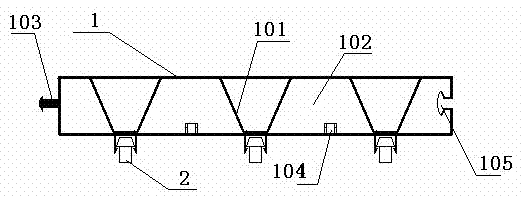
[0021] A rapid positioning method for a floor and a floor support body, comprising at least a floor 1 and a floor support body 2, the movement surface of the floor 1 is flat, and guide grooves 106 are distributed parallel to the ground at intervals, the diameter of the guide groove 106 is small at the top and large at the bottom , the floor support body 2 is connected with the guide groove 106, and distributed under the floor 1 to form uniform force points.

Embodiment 2

[0023] like figure 1 As shown, a quick positioning method for a floor and a floor support includes at least a floor 1 and a floor support 2. The moving surface of the floor is flat, and guide grooves 106 are distributed parallel to the ground at intervals. The upper diameter of the guide groove is small, and the lower diameter Large, the floor support body 2 is connected with the guide groove 106 grooves, and is distributed into uniform stress points under the floor.

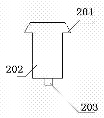
[0024] like figure 2 As shown, the floor support body 2 includes a top end 201 and a bottom end 202, and the floor support body 2 is made of silicon rubber material, which is molded to make the whole floor elastic. The diameter of the top end 201 is larger in the horizontal direction, and the diameter of the bottom end 202 is smaller than the width of the guide groove 106 in the horizontal direction.

[0025] like Figure 5 As shown, the top end 201 has a protrusion 203 on it, and the top end 201 and the top...

Embodiment 3

[0030] Different from Embodiment 2, the top end 201 of the floor support body 2 is a left-right symmetrical trapezoid. The trapezoid is smaller than the space of the guide groove 106 .


PUM


Abstract

The invention relates to a rapid positioning method of a floor and a floor supporting body, at least comprising the floor and the floor supporting body. The rapid positioning method is characterized in that guide grooves are distributed on the grounded surface of the floor at intervals; the diameter of the upper side of each guide groove is small and the diameter of the lower side of each guide groove is large; the floor supporting body is connected with the guide grooves; connecting holes are connected in front and back of the floor; one end of a connecting piece is provided with a convex column and the other end of the connecting piece is provided with a hole; one end of the connecting piece is movably positioned together with the connecting holes of the front and back floors through the convex column and the other end of the connecting piece is in threaded connection with the connecting holes through a screw; and tempered threads are sleeved in the connecting holes, so that the connection of the screw is reliable. The movable floor disclosed by the invention is low in cost and short in building period, is easy to maintain and has high low requirements on the ground surface.

Description

technical field [0001] The invention relates to a sports floor, in particular to a quick positioning method for a floor and a floor support body. Background technique [0002] With the development of various fitness sports, people have higher requirements for the ground conditions of sports, and smoothness, easy cleaning and good elasticity have become the most basic requirements. [0003] There are a large number of supporting sports floors in the indoor environment. These floors can meet the requirements of flatness, easy cleaning, and good elasticity. However, the existing sports floors provided in the outdoor environment have high requirements on the ground, which increases the cost and maintenance costs. Its market space is limited. Contents of the invention [0004] The invention provides a quick positioning method for a floor and a floor support body with low cost, short construction period, easy maintenance and low requirements on the ground. [0005] The object ...

Claims


Application Information

Patent Timeline
Patent Type & Authority Patents(China)
IPC IPC(8): E04F15/02E04F15/10E04F15/22
Inventor 岑海超崔红忠
Owner 朱庆
Learn More