
Tire deburring device and method

A technology for deburring and tires, applied in tires, household appliances, metal processing, etc., can solve problems such as low production efficiency, unguaranteed safety, and tread damage, so as to improve work efficiency, increase the scope of application, The effect of improving machining accuracy

Pending Publication Date: 2020-11-10
QINGDAO UNIV OF SCI & TECH
View PDF9 Cites 5 Cited by
  • Summary
  • Abstract
  • Description
  • Claims
  • Application Information

AI Technical Summary

Problems solved by technology

[0002] The number of cars in our country is increasing year by year, and the demand for tires is increasing rapidly. However, after the current car tires are produced, there will be a lot of needle-shaped and side-shaped burrs on the sidewalls of the tires, which will seriously affect the aesthetics of the tires. satisfy customer's request
However, the commonly used tire deburring technology is mainly for workers to cut slowly with special knives in their hands. This method is not only labor-intensive for workers, safety cannot be guaranteed, but also production efficiency is not high, which is not conducive to ensuring product processing precision
There are also manufacturers who design machinery and equipment to use rough rubber rollers to generate friction to remove tire burrs or use high-pressure water to remove tire burrs, but it is easy to damage the tread while removing the tread burrs, which will affect the quality of the tire.

Method used


Image

  • Tire deburring device and method
  • Tire deburring device and method
  • Tire deburring device and method

Examples


Embodiment 1

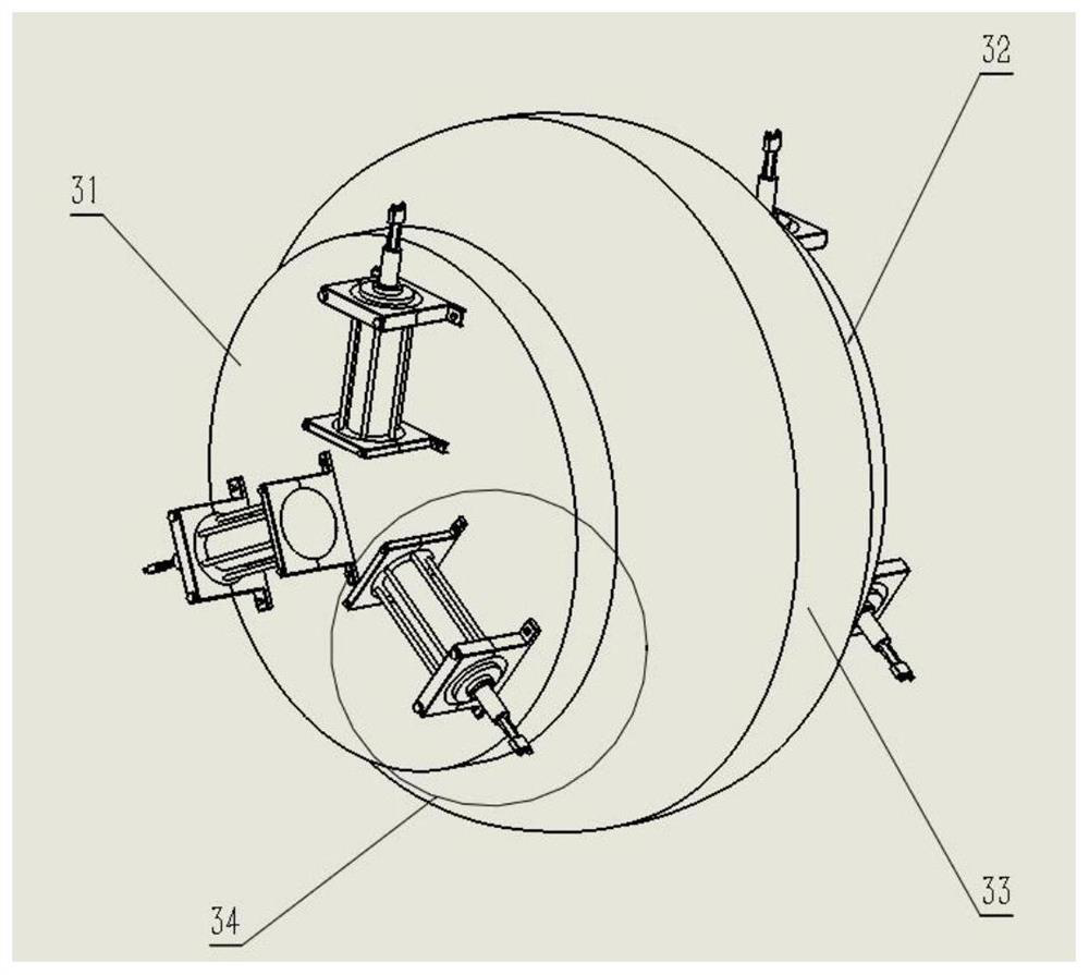
[0044] 1. When the two 135 / 80R12 tires to be processed are sent to the upper and lower stations on the right, the right tire clamping device is activated, and the two tires are respectively set on the upper and lower airbags on the right, and are inflated by the air pump. The air at 240KPa supports the inner surface of the tire, and the plunger in the telescopic cylinder has a stroke of 5mm, so that the distance between the front end cover and the rear end cover changes, so as to adapt to the tire section width of 135 / 80R12 tire to be processed, which is 135mm. The cylinder in the mouth support mechanism pushes the electric gripper to clamp the tire mouth, and the electric gripper adapts to the width of the mouth of the tire to be processed to 20mm, so as to complete the fixing of the tire to be processed.

[0045] 2. The right tire clamping and rotating device is started, and the first driving motor provides a speed of 1440r / min. After the deceleration mechanism, the rotating ...

Embodiment 2

[0051] 1. When the two 225 / 45R16 tires to be processed are sent to the upper and lower stations on the right, the right tire clamping device is activated, and the two tires are respectively set on the upper and lower airbags on the right, and are filled by the air pump. The air at 250KPa supports the inner surface of the tire, and the plunger in the telescopic cylinder has a stroke of 95mm, so that the distance between the front end cover and the rear end cover changes, so as to adapt to the tire section width of 225 / 45R16 tire to be processed, which is 225mm. The cylinder in the mouth support mechanism pushes the electric grippers to clamp the rim of the tire, and the electric gripper adapts to the width of the rim of the tire to be processed at 25 mm, so as to complete the fixing of the tire to be processed.

[0052] 2. The right tire clamping and rotating device is started, and the first driving motor provides a speed of 1440r / min. After the deceleration mechanism, the rotatin...


PUM

PropertyMeasurementUnit
Diameteraaaaaaaaaa
Widthaaaaaaaaaa

Abstract

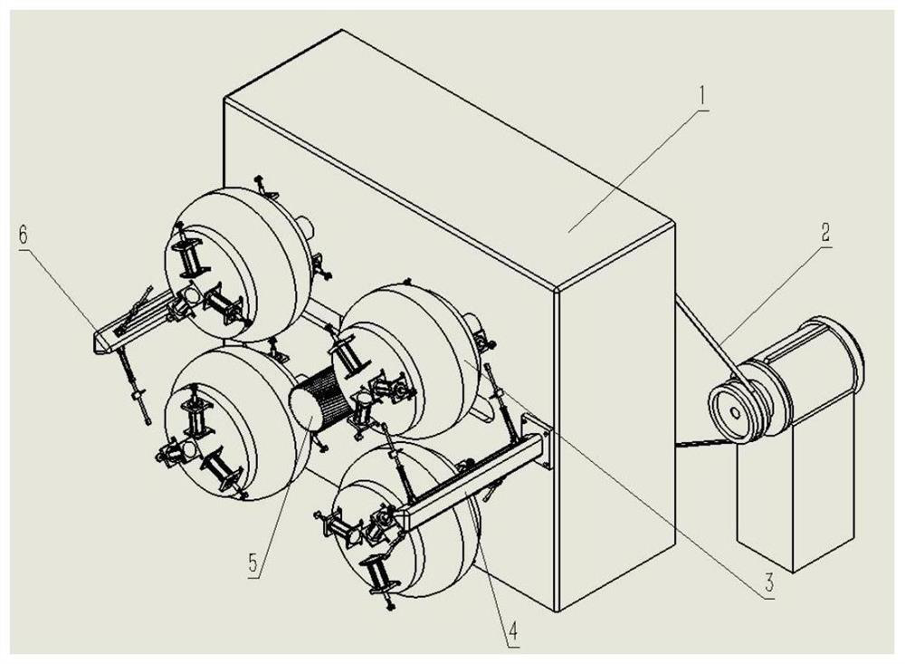
The invention provides a tire deburring device and method. The device comprises a rack, a tire clamping device, a tire clamping rotating device, a tread deburring mechanism and sidewall deburring mechanisms. The device and the method are used for solving the problems of low production efficiency, low precision and limited application range of production equipment in existing tire deburring procedures. The tire deburring device has four stations, the two left stations and the two right stations are distributed up and down, and the stations on the left side and the stations on the right side work intermittently; the tread deburring mechanism is arranged in the center of the rack; the two sidewall deburring mechanisms are arranged on the stations on the left side and the stations on the rightside correspondingly;the specific positions of the tread deburring mechanism and the sidewall deburring mechanisms in the working process are determined by the model of a to-be-machined tire, and speed changing devices are arranged in the sidewall deburring mechanisms, so that a tread deburring cutter has the effects of slow advancing and quick retreating, the efficiency is ensured, and meanwhile, the to-be-machined surface of the tire is not prone to scratching; the flatness of the to-be-machined surface of the to-be-machined tire can be guaranteed while the to-be-machined tire is fixed by the tire clamping device, so that the machining precision can be improved; and according to the provided production method, the whole machining process can be uninterrupted, and the working efficiencycan be increased by 50% or above.

Description

technical field [0001] The invention relates to the field of tire production, processing and manufacturing, in particular to a tire deburring device. Background technique [0002] The number of cars in our country is increasing year by year, and the demand for tires is increasing rapidly. However, after the current car tires are produced, there will be a lot of needle-shaped and side-shaped burrs on the sidewalls of the tires, which will seriously affect the aesthetics of the tires. satisfy customer's request. However, the commonly used tire deburring technology is mainly for workers to cut slowly with special knives in their hands. This method is not only labor-intensive for workers, safety cannot be guaranteed, but also production efficiency is not high, which is not conducive to ensuring product processing precision. There are also manufacturers who design machinery and equipment to use rough-surfaced rubber rollers to generate friction to remove tire burrs or use high-...

Claims


Application Information

Patent Timeline
IPC IPC(8): B29C37/02B26D1/18B26D7/02B26D5/08B29L30/00
CPCB29C37/02B26D1/18B26D7/02B26D5/086B29L2030/00
Inventor 焦冬梅苑诗帅田仲可
Owner QINGDAO UNIV OF SCI & TECH
Learn More