Servo hydraulic cylinder

A hydraulic cylinder and cylinder body technology, applied in the field of hydraulic cylinders, can solve problems such as connection failure, connection instability, guide sleeve seal failure, etc., and achieve the effects of reducing frictional heat, good working environment, and improving buffering effect

Inactive Publication Date: 2020-11-06
芜湖力维胜机械设计有限公司
View PDF0 Cites 0 Cited by
  • Summary
  • Abstract
  • Description
  • Claims
  • Application Information

AI Technical Summary

Problems solved by technology

[0003] In the process of realizing the present invention, the inventor found that at least the following problems in the prior art have not been solved: 1. When the existing hydraulic cylinder is working, there will be friction between the piston rod and the guide sleeve, and in order to ensure that the guide sleeve and the piston The seal between the rods, usually the fit between the two is relatively tight, which leads to greater friction between the two, and a large amount of heat will be generated during friction. The heat generated needs to be dissipated in time, otherwise it will accumulate It will make the hydraulic oil viscous and reduce the mechanical efficiency of the cylinder. In addition, excessive heat will damage the sealing ring, thereby destroying the sealing system of the cylinder and affecting the normal use of the cylinder. Impact and wear will cause the seal of the guide sleeve to fail, resulting in hydraulic oil leakage. At the same time, the impact will cause instability in the connection between the guide sleeve and the cylinder body, and even damage the connecting thread, resulting in failure of the connection

Method used


Image

  • Servo hydraulic cylinder
  • Servo hydraulic cylinder
  • Servo hydraulic cylinder

Examples


Embodiment Construction

[0034] The following will clearly and completely describe the technical solutions in the embodiments of the present invention with reference to the accompanying drawings in the embodiments of the present invention. Obviously, the described embodiments are only some, not all, embodiments of the present invention. Based on the embodiments of the present invention, all other embodiments obtained by persons of ordinary skill in the art without making creative efforts belong to the protection scope of the present invention.

[0035] see Figure 1 to Figure 6 , the present invention provides a servo hydraulic cylinder technical solution:

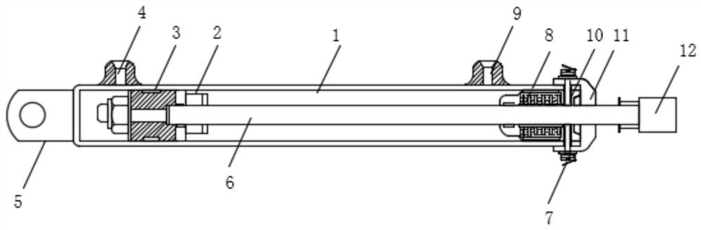
[0036] A servo hydraulic cylinder, such as figure 1 As shown, it includes a cylinder 1, one end of the cylinder 1 is provided with a first connection end 5, the other end of the cylinder 1 is fixedly installed with a top cover 11, and one end of the cylinder 1 is slidably provided with a piston 3 , one end edge of the piston 3 is provided with a...


PUM


Abstract

The invention discloses a servo hydraulic cylinder. The servo hydraulic cylinder comprises a cylinder body; one end of the cylinder body is provided with a first connection end, and the other end of the cylinder body is fixedly equipped with a head cover; a piston is slidably arranged at one end inside the cylinder body; a protective device is arranged at the edge of one end of the piston; a piston rod is fixedly installed at the middle position of one end of the piston; a guide sleeve is fixedly installed at the other side of the inside of the cylinder body; one end of the piston rod penetrates through the guide sleeve and the head cover and is fixedly connected with a second connection end; and a groove is embedded inside the guide sleeve. According to the servo hydraulic cylinder provided by the invention, a heat conducting plate, a heat conducting column, a heat conducting adhesive and a heat dissipating plate can be arranged, heat generated by the guide sleeve and the piston rod is sealed and exported, the heat is prevented from accumulating at the connecting position of the guide sleeve and the piston rod, so that hydraulic oil becomes viscous, the mechanical efficiency of the cylinder is reduced, and meanwhile, the problem that excessive heat damages a seal ring and destroys a sealing system of the cylinder is avoided.

Description

technical field [0001] The invention relates to the technical field of hydraulic cylinders, in particular to a servo hydraulic cylinder. Background technique [0002] The hydraulic cylinder is the executive element in the hydraulic transmission system. It is an energy conversion device that converts hydraulic energy into mechanical energy. The hydraulic motor realizes continuous rotary motion, while the hydraulic cylinder realizes reciprocating motion. The structure of the hydraulic cylinder has a piston Cylinder, plunger cylinder, swing cylinder three categories, piston cylinder and plunger cylinder to achieve reciprocating linear motion, output speed and thrust, swing cylinder to achieve reciprocating swing, output angular velocity and torque, hydraulic cylinder can be used in addition to single Two or more are combined or used in combination with other mechanisms to complete special functions. The hydraulic cylinder has a simple structure and reliable operation, and has b...

Claims


Application Information

Patent Timeline
Patent Type & Authority Applications(China)
IPC IPC(8): F15B15/14F15B15/20
CPCF15B15/1423F15B15/1471F15B15/1485F15B2215/30
Inventor 周云飞陈璐周民强
Owner 芜湖力维胜机械设计有限公司
Why Eureka
Try Eureka