Efficient multi-stage braking mechanism

A braking mechanism, efficient technology

Pending Publication Date: 2020-11-06
DALIAN UNIV OF TECH
View PDF1 Cites 1 Cited by
  • Summary
  • Abstract
  • Description
  • Claims
  • Application Information

AI Technical Summary

Problems solved by technology

[0011] (1) Since the maximum braking speed of the engine is much higher than the rated speed, especially for small-displacement engines, an excessively high braking speed will cause the pure hydraulic brake mechanism to fail to work normally due to pumping and other reasons
[0012] (2) In the brake mode, the pressure in the cylinder near the compression top dead center or each top dead center is very high and the pressure fluctuates violently, and the brake mechanism needs to overcome the very large and high-frequency changing gas force to open the valve; and At the same time, the pressure in the cylinder increases with the increase of the speed, the engine braking speed is extremely high, the force of the braking mechanism is very strict, and the failure rate of related parts is very high. Therefore, its reliability design is a difficult problem in the industry
The existing problems are: (a) The pressure in the cylinder near the top dead center is very high, which causes serious lift loss in the valve lift curve generated by the mechanism, that is, the valve cannot maintain a large lift, resulting in large braking power The amplitude decreases and the maximum cylinder pressure increases rapidly in the braking high-speed area
The existing problems are: (a) The maximum cylinder pressure is high, and the force on the braking mechanism is large
However, there are still the following problems to be improved: (a) As can be seen from the above structure and switching process, it is necessary to ensure that the locking element can smoothly move back and forth between the ring groove of the inner plunger and the groove of the drive piston assembly wall, that is, the smooth switching requirement When the locking element is in contact with the ring groove of the inner plunger, the line of action of the resultant force is outside the friction angle, otherwise self-locking occurs; similarly, when the locking element is in contact with the groove of the wall of the driving piston assembly, the line of action of the resultant force It must also be outside the friction angle, otherwise self-locking will occur. Therefore, the locking element needs to adopt a specially designed shape such as a wedge, a roller or a ball, and the groove of the inner plunger ring and the groove of the drive piston assembly wall also need to be specially designed. design; the existing composite braking mechanism only adopts hydraulic transmission during the switching process, and adopts mechanical transmission after the switching is completed, and the impact of gas force will directly act on the braking mechanism; the above-mentioned anti-self-locking design causes the locking element The resultant force of the force between the plunger ring grooves and the force between the locking element and the groove of the drive piston assembly wall is much greater than the force of the valve to the drive piston, and the corresponding contact stress is greatly increased; especially When applied to the brake mechanism on the exhaust side, the reliability is difficult to guarantee, and after a long time of work, deformation between the locking element and the groove on the wall of the driving piston assembly is easy to occur, which further causes the locking element and the wall of the driving piston assembly to be deformed. The actual shape of the slot on the engine gradually deviates from the designed shape and becomes stuck, which eventually leads to serious failures such as engine failure
(b) Whether the locking element is in the ring groove of the internal plunger spring or in the groove of the drive piston assembly wall, the locking element cannot In contact with the entire length of the hole on the drive piston, the small contact surface will further lead to very large contact stress, which is extremely detrimental to the reliability and life of the locking element and drive piston
(c) In order to ensure the reliability of the mechanism, the size of the mechanism will be greatly increased, which will make it difficult to meet the engine installation requirements

Method used


Image

  • Efficient multi-stage braking mechanism
  • Efficient multi-stage braking mechanism
  • Efficient multi-stage braking mechanism

Examples


Embodiment 1

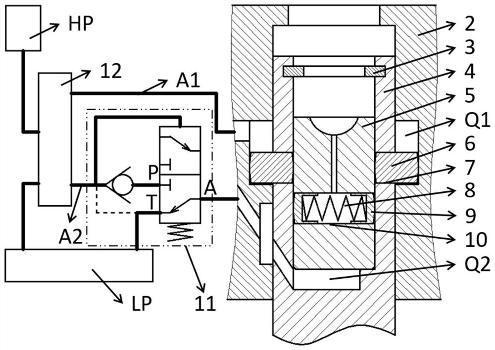
[0052] figure 1 It is a structural schematic diagram of Embodiment 1 of this mechanism. Such as figure 1 It can be seen that the mechanism includes a housing 2 , a plunger sleeve 4 arranged on the housing 2 and reciprocating relative to the housing 2 , a plunger 5 arranged on the plunger sleeve 4 and reciprocating relative to the plunger sleeve 4 , and a hydraulic control unit 12 . A second oil chamber Q2 is formed between the plunger 5 and the plunger sleeve 4 . A collar is provided on the plunger sleeve 4 as a limit setting for limiting the maximum volume of the second oil chamber Q2. Two first passages 7 are arranged on the side wall of the plunger sleeve 4 , and each first passage 7 is provided with a locking body 6 that reciprocates relative to the first passage 7 . A first oil chamber Q1 is formed between the plunger sleeve 4 , the housing 2 and the locking body 6 . The hydraulic control unit 12 is connected to the first oil chamber Q1 through the first oil passage...

Embodiment 2

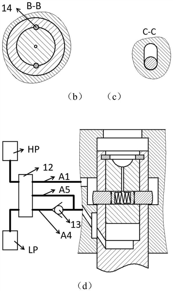
[0059] image 3 It is a structural schematic diagram of Embodiment 2 of this mechanism. Such as image 3 It can be seen that the mechanism includes a housing 2 , a plunger sleeve 4 fixed on the housing 2 , a plunger 5 arranged on the plunger sleeve 4 and reciprocating relative to the plunger sleeve 4 , and a hydraulic control unit 12 . A second oil chamber Q2 is formed between the plunger 5 and the plunger sleeve 4 . A shoulder is set on the plunger sleeve 4 to limit the limit setting of the maximum volume of the second oil chamber Q2. Three first passages 7 uniformly distributed in the circumferential direction are arranged on the side wall of the plunger sleeve 4 , and each first passage 7 is respectively provided with a locking body 6 that reciprocates relative to the first passage 7 .

[0060] image 3 The third reset scheme is adopted, the side wall of the plunger 5 is provided with a circumferential groove, the third oil chamber Q3 is arranged between the plunger 5, ...


PUM


Abstract

The invention provides an efficient multi-stage braking mechanism. The efficient multi-stage braking mechanism comprises a shell, a plunger sleeve, a plunger and a hydraulic control unit. The plungersleeve is arranged on the shell and is fixed to or reciprocates relative to the shell. The plunger is arranged on the plunger sleeve and reciprocates relative to the plunger sleeve. At least one firstchannel is arranged on the side wall of the plunger sleeve. A locking body reciprocating relative to the first channel is arranged in the first channel. The hydraulic control unit is connected with asecond oil cavity formed between the plunger and the plunger sleeve, and is also connected with a first oil cavity formed among the plunger sleeve, the shell and the locking body. The failure mode, the first active mode and the second active mode are achieved by adjusting the communication relationship between each oil cavity and a low-voltage source and a high-voltage source. The mechanism is compact in size and high in reliability. Compact mounting of an engine and other requirements such as using original gas distribution mechanism spare parts as much as possible are realized and met by replacing some spare part of the original gas distribution mechanism. Multi-stage braking of the engine and ultra-low-cost upgrading of products are realized. The mechanism is very beneficial to productpopularization and application.

Description

technical field [0001] The invention relates to the technical field of engine variable valve mechanism, in particular to a high-efficiency multi-stage brake mechanism. Background technique [0002] With the development of vehicle energy saving and emission reduction technology, the braking capacity of the vehicle itself decreases; and with the increase of vehicle weight and vehicle speed, the demand for braking power increases, which requires the braking system to provide greater braking power . Due to the problem that the main braking system and the retarder assembled on the vehicle transmission system are prone to heat degradation after long-term operation, the braking power is rapidly reduced or even the brake fails, and the service life of the braking system is greatly reduced. In this context, engine braking, which does not have the problem of thermal fading, has become one of the key technologies for vehicle braking. [0003] Improving engine braking power and variab...

Claims


Application Information

Patent Timeline
Patent Type & Authority Applications(China)
IPC IPC(8): F01L13/06F01L13/00F01L1/26F01L9/02
CPCF01L13/06F01L13/0015F01L1/26
Inventor 崔靖晨隆武强孟相宇礼博田华王阳
Owner DALIAN UNIV OF TECH
Why Eureka
Try Eureka