
Traffic sound barrier based on vibration pollution prevention and control technology

A pollution prevention and sound barrier technology, applied in the direction of electric components, noise absorbing devices, lighting device components, etc., can solve the problems of inability to convert energy into self-use, sound barrier consumes energy, and has little effect, so as to improve Energy conversion efficiency, improvement of sound insulation effect, and effect of increasing power generation

Inactive Publication Date: 2020-11-06
何少振
View PDF6 Cites 0 Cited by
  • Summary
  • Abstract
  • Description
  • Claims
  • Application Information

AI Technical Summary

Problems solved by technology

[0003] For residents living along roads or railways, they have been suffering from vibrations, mainly due to the relatively large impact of noise caused by vibrations. Although there are sound barriers, the effect is minimal, and the existing sound barriers are only A single sound insulation function cannot convert the energy generated in the vibration process into its own use, resulting in additional energy consumption when adding other functions to the sound barrier, which does not conform to the concept of energy conservation and environmental protection

Method used


Image

  • Traffic sound barrier based on vibration pollution prevention and control technology
  • Traffic sound barrier based on vibration pollution prevention and control technology
  • Traffic sound barrier based on vibration pollution prevention and control technology

Examples


Embodiment 1

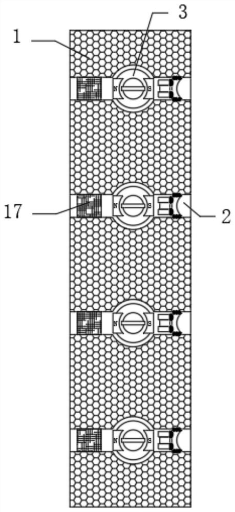
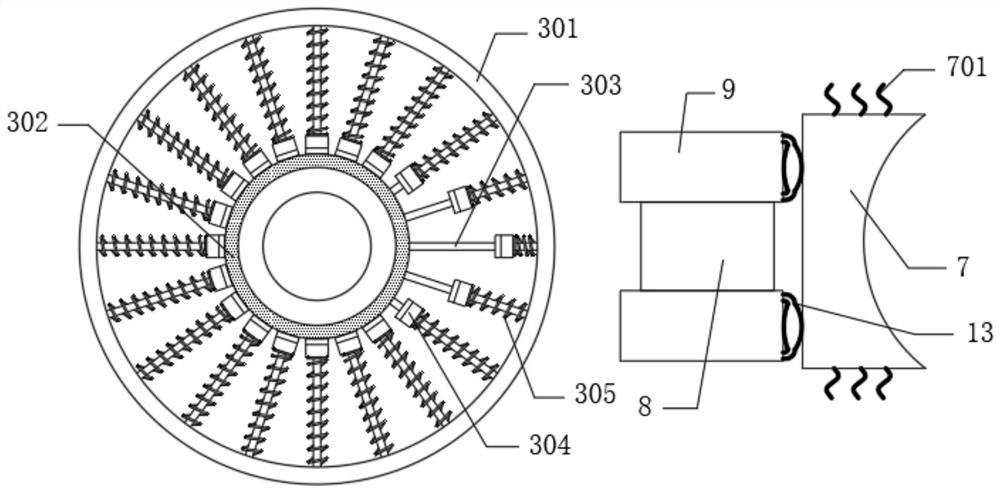
[0045] see Figure 1-11 , a traffic sound barrier based on vibration pollution prevention technology, see Figure 1-2 , including the sound barrier body 1, the inner wall of the sound barrier body 1 is provided with a cross cavity 2, and the middle part of the cross cavity 2 is provided with a spherical cavity, and a magnetic dynamic ball 3 is installed in the spherical cavity, and the cross cavity 2 is far away from the inner wall of the magnetic dynamic ball 3 The sound-absorbing cotton 17 is fixedly connected, and the sound-absorbing cotton 17 can further consume the vibration that is not consumed by the vibration block 7, and improve the sound insulation effect of the sound barrier body 1. Electromagnetic induction power generation devices 4 are installed on both sides of the cross cavity 2, and the magnetic power Both sides of the ball 3 are fixedly connected to the closed coil of the electromagnetic induction power generation device 4. The interior of the sound barrier b...


PUM


Abstract

The invention discloses a traffic sound barrier based on a vibration pollution prevention and control technology, and belongs to the technical field of vibration pollution prevention and control. According to the invention, a sound barrier is combined with a magnetic perpetual motion machine and a power generation device, vibration energy is converted into driving force of the magnetic perpetual motion machine to drive the power generation device to generate power, and the electric energy can supply power to a landscape lamp strip, thereby conforming to the concept of energy conservation and environmental protection, and achieving full utilization of resources; and a water squeezing bag is extruded through the vibration of a vibration block, the water squeezing bag supplies water to a magnetic adjusting plate, water is guided to the upper part of a magnetism isolating plate by utilizing the water absorption performance of a water storage ball and a main water diversion belt, the magnetism isolating plate is rotationally opened according to the lever principle, and second magnets attract the magnet sliding sleeve, so that the attraction force of the two second magnets and the firstmagnet to the magnet sliding sleeve can be increased so as to improve the rotating speed of the magnetomotive ball and further improve the power generation capacity. Compared with the prior art, the sound barrier is additionally provided with a power generation function, resources are fully utilized, and the energy conversion efficiency is further improved.

Description

technical field [0001] The invention relates to the technical field of vibration pollution prevention and control, and more specifically relates to a traffic sound barrier based on the vibration pollution prevention technology. Background technique [0002] The process in which the state of motion of an object changes alternately between maximum and minimum values ​​over time is called vibration. Excessive vibration can cause discomfort, fatigue, and even physical injury. Secondly, vibration will form a noise source, affecting or polluting the environment in the form of noise. Environmental vibration is an aspect of environmental pollution. Railway vibration, highway vibration, subway vibration, and industrial vibration will all have adverse effects on people's normal life and rest. [0003] For residents living along roads or railways, they have been suffering from vibrations, mainly due to the relatively large impact of noise caused by vibrations. Although there are soun...

Claims


Application Information

Patent Timeline
Patent Type & Authority Applications(China)
IPC IPC(8): E01F8/00F21V33/00H02K7/18
CPCE01F8/00E01F8/0005E01F8/0023F21V33/00H02K7/1876
Inventor 何少振
Owner 何少振
Learn More