
Oil stain adsorption device for non-planar metal workpiece

A technology of metal workpieces and adsorption devices, which is applied in the field of powder steel processing devices, can solve the problems of waste of manpower, large limitations, and difficulty in removal, and achieve the effect of convenient power connection and power disconnection

Inactive Publication Date: 2020-11-06
何安静
View PDF0 Cites 0 Cited by
  • Summary
  • Abstract
  • Description
  • Claims
  • Application Information

AI Technical Summary

Problems solved by technology

[0003] Powder metallurgy driven gear parts, due to the particularity of the material, are formed by pressing and sintering extremely fine alloy powder particles. There are certain pores between the material particles. And shaving oil will seep into the product matrix from the pores, and after the high-frequency quenching and tempering process, the oil in the matrix will seep out from the pores due to high temperature, and condense on the surface of the workpiece to form oil stains, resulting in yellowing appearance. The appearance defect of uneven color; and it is very obvious and difficult to remove
[0004] The current degreasing of metal workpieces formed by powder metallurgy is mostly through manual use of oil-absorbing sponges for physical wiping, or using carburetors for degreasing through chemical reactions, but for larger metal workpieces, manual wiping It is time-consuming, labor-intensive and manpower-intensive. In addition, the sponge and the workpiece cannot be completely bonded during the erasing process, and the degreasing by spraying the oil can not guarantee the complete elimination of oil stains in the gaps of the workpiece, which has great limitations.

Method used


Image

  • Oil stain adsorption device for non-planar metal workpiece
  • Oil stain adsorption device for non-planar metal workpiece
  • Oil stain adsorption device for non-planar metal workpiece

Examples


Embodiment 1

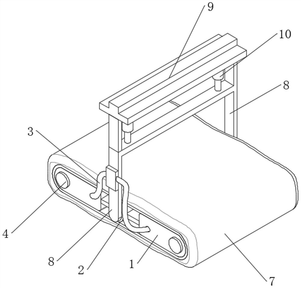
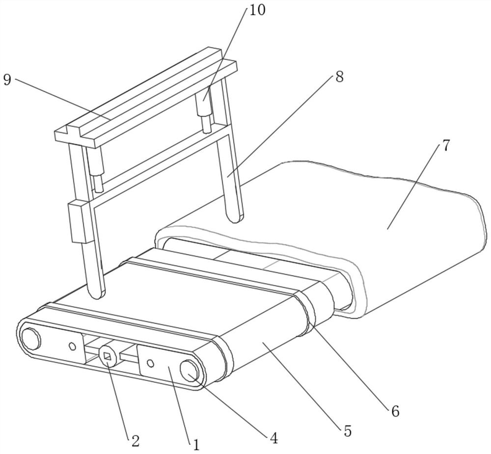
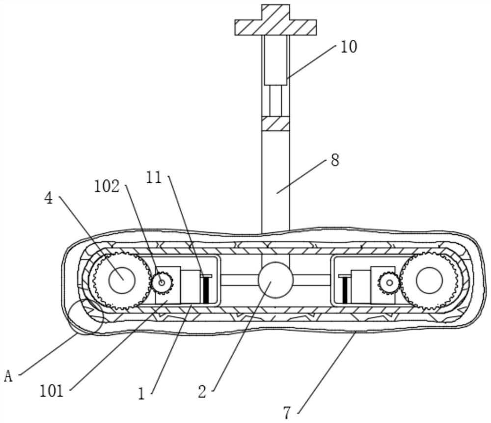
[0038] see Figure 1-3 and Figure 6, an oil dirt adsorption device for non-planar metal workpieces, comprising a pair of housings 1, a central shaft 2 is arranged between the pair of housings 1, the central shaft 2 includes a connecting shaft 201, and both sides of the connecting shaft 201 are provided There is a motor 202, a hinged plate 203 is fixedly connected to the power output end of the connecting shaft 201, the hinged plate 203 is fixedly connected to the housing 1, and a support 8 is connected between the two connecting shafts 201; a power supply is connected to the support 8, and the power supply and A conductive wire 3 is connected between the shells 1, and a fixed plate 9 is fixedly connected to the upper end of the bracket 8. A person skilled in the art designs an electric guide rail that matches the workpiece, and then the fixed plate 9 is slidably connected to the electric guide rail, so that the device It can move along the designated route. The route design ...


PUM


Abstract

The invention discloses an oil stain adsorption device for a non-planar metal workpiece, and belongs to the field of powder steel processing devices. The oil stain adsorption device for the non-planarmetal workpiece comprises a pair of shells, wherein a central shaft is arranged between the pair of shells; the central shaft comprises a connecting shaft, and motors are arranged on two sides of theconnecting shaft; power shafts are rotationally connected in the shells, servo motors matched with the power shafts are fixedly connected in the shells, and driving gears are connected between the power output ends of the servo motors and the power shafts; and a movable caterpillar band matched with the power shafts is connected between the two shells, a pair of conductive bands are fixedly connected to the movable caterpillar band, and an adsorption body is fixedly connected to the surface of the movable caterpillar band. An adsorption film can be attached to the surface of non-planar metalthrough magnetic fluid, so that it is guaranteed that oil stain on the surface of the metal sufficiently permeates into the adsorption body; and the oil in the adsorption body and an activating agenton the magnetic fluid are subjected to a hydrolysis reaction, so that the oil is eliminated.

Description

technical field [0001] The invention relates to the field of powder steel processing devices, and more specifically relates to an oil dirt adsorption device for non-planar metal workpieces. Background technique [0002] Powder metallurgy is a process technology for producing metal powder or using metal powder (or a mixture of metal powder and non-metal powder) as raw material, forming and sintering to manufacture metal materials, composite materials and various types of products. The powder metallurgy method has similarities with the production of ceramics, and both belong to the powder sintering technology. Therefore, a series of new powder metallurgy technologies can also be used for the preparation of ceramic materials. Due to the advantages of powder metallurgy technology, it has become the key to solve the problems of new materials and plays a pivotal role in the development of new materials. [0003] Powder metallurgy driven gear parts, due to the particularity of the...

Claims


Application Information

Patent Timeline
Patent Type & Authority Applications(China)
IPC IPC(8): C23G3/00
CPCC23G3/00
Inventor 何安静
Owner 何安静
Learn More