Ampoule bottle chain conveying device

A technology of chain conveying device and chain conveyor, applied in the direction of conveyor, transportation and packaging, packaging, etc., can solve the problems of inconvenient operation, rupture of ampoules, backlog of ampoules, etc., to achieve the effect of convenient installation and guaranteed stability.

Pending Publication Date: 2020-11-06
ZHENGZHOU SHUNYI TECH CO LTD
View PDF1 Cites 0 Cited by
  • Summary
  • Abstract
  • Description
  • Claims
  • Application Information

AI Technical Summary

Problems solved by technology

For example, "the application number is 201610386111.X, and the patent name is a high-definition printing machine for small-capacity injection ampoule bottles in a pharmaceutical factory". The plate and the printing machine chain cooperate to ensure that the ampoule bottle will not break away from the printing machine chain, and continue to be driven by the printing machine chain until the lower end of the crescent-shaped guide plate is separated from the printing machine chain; but because the crescent-shaped guide plate is a fixed plate, although it can The size of the bottle is adjusted by adjusting the distance between the crescent-shaped guide plate and the chain paper to adapt to ampoules of different sizes, but the adjustment is very troublesome and inconvenient to operate. In addition, when the ampoules transported by the conveyor are of different sizes, the small-sized The ampoules may fall off the chain, the ampoules cannot enter the packaging box in an orderly manner, and even the ampoules may accumulate and pile up on each other, causing the ampoules to break. At the same time, the existing ampoule conveying mechanism cooperates with the lifting device of the printing machine to adjust the lifting force. Affect the printing effect

Method used


Image

  • Ampoule bottle chain conveying device
  • Ampoule bottle chain conveying device
  • Ampoule bottle chain conveying device

Examples


Embodiment 1

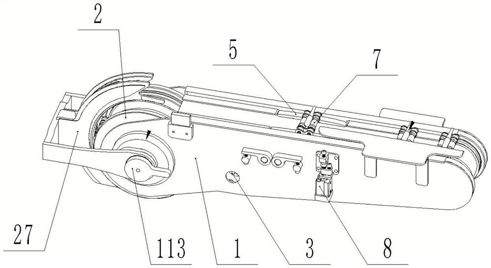
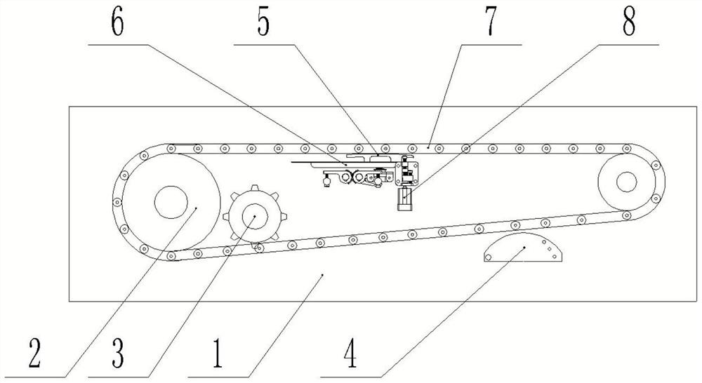
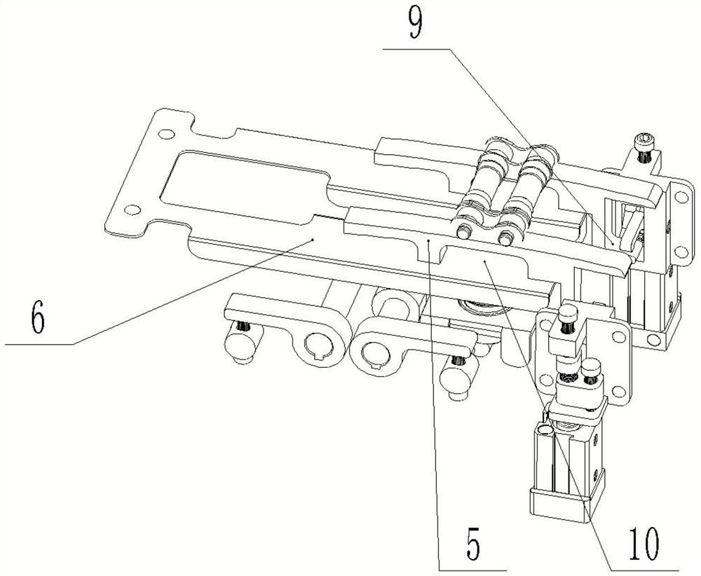
[0033] Such as Figure 1-5 The shown chain springing device for ampoule bottle conveyor includes a frame 1, a driving wheel 3 and a driven wheel 2 are installed in the frame, and a double-row conveying chain 7 is set on the driving wheel 3 and the driven wheel 2. The wheel is connected with a driving motor, the driving motor drives the driving wheel to rotate, the driving wheel and the driven wheel drive the double-row conveying chain to rotate, the ampoule bottle is placed in the groove formed by the double-row conveying chain, and the chain tensioning device is also installed on the frame 4. The chain tensioning device 4 includes a semi-cylindrical tensioning block. The top of the tensioning block is installed with a supporting part to support the conveying chain. One side of the tensioning block is rotated and installed on the frame. hole, by changing the installation position of the adjustment hole, and then changing the support height of the support part of the tension bl...


PUM


Abstract

The invention discloses an ampoule bottle chain conveying device, and relates to the technical field of pharmaceutical machines. The device comprises a rack. A chain conveyor for conveying ampoule bottles is arranged on the rack. A crescent-shaped bottle stopping mechanism matched with the chain conveyor is arranged at the bottle discharging side, corresponding to the chain conveyor, of the rack.The crescent-shaped bottle stopping mechanism comprises an installing base for being installed on the chain conveyor. An arc guiding opening is formed in the installing base. An elastic bottle pressing device is arranged at the guiding opening. The elastic bottle pressing device comprises a plurality of sets of crescent-shaped leaf springs arranged in the guiding opening. Any set of crescent-shaped leaf springs can move along the radial line of a crescent-shaped. An elastic device is connected to each set of crescent-shaped leaf spring. A chain wear-resisting strip for supporting a conveying chain is arranged under the conveying face, on the chain conveyor, of the rack. A chain supporting mechanism for driving the chain to ascend and descend is arranged at the portion, between every two adjacent chain wear-resisting strips, in the middle of the rack. The device has the effects of being high in conveying efficiency and stable in bottle conveying.

Description

technical field [0001] The invention relates to the field of ampoule bottle processing equipment, in particular to a conveying device for conveying ampoule bottles. Background technique [0002] Ampoule bottle is widely used as a packaging container in pharmaceutical packaging. The text information on its surface includes the name, capacity, production date, batch number of the drug, etc., which are related to the life safety of the user. Correspondingly, the printing of these information needs and ampoule bottle printer to complete. The ampoule bottle printing machine mainly includes the ampoule bottle conveying mechanism and the printing mechanism. The ampoule bottle conveying mechanism drives the ampoule bottle to move, and the bottle body is printed by the printer. After the printing is completed, the conveyer will automatically drop the ampoule bottle into the Packing box, so as to complete the printing of the ampoule bottle body and the packaging of the bottle body. ...

Claims


Application Information

Patent Timeline
IPC IPC(8): B65G23/06B65G21/20B65G23/44B65B21/02B65B21/04
CPCB65B21/02B65B21/04B65G21/209B65G23/06B65G23/44B65G2201/0244
Inventor 刘丙炎
Owner ZHENGZHOU SHUNYI TECH CO LTD
Why Eureka
Try Eureka